In an attempt to make the necessary wiring modifications easier to understand, we have divided the information into 3 sections...
...'94-'96 LT1 Stock Harness & Connector Guide...
...Wiring Connections & Modifications...
...'93-'95 RX-7 Harness & Connector Guide...
The basic idea is to take LT1 connectors/terminals identified in the top section, apply the connection info in the middle section, and connect them to the RX-7 connectors/terminals identified in the bottom section.
The LT1 harness basically connects to the rest of the car thru a few specific connectors. The first two are located close together in the area of right shock tower...
...C100...black 10 pin connector.
............A- pink (injectors 2/3/5/8 ign/inj switched 12v 7.5amp power in)
............B- dk green w/ white stripe (AC comp relay control, PCM grounds to turn on AC)
............C- dk green (AC comp clutch status signal into PCM)
............E- brown (air pump relay control)
............F- brown (power in for fans, EVAP, EGR, skip shift, reverse solenoid)
............G- pink (switched 12v 15amp power in)
............H- dk blue (coolant fan 2 & 3 relay control out)
............J- dk green (cooling fan 1 relay control out, PCM grounds to turn on a primary cooling fan)
............K- pink (injectors 1/4/6/7 ign/inj switched 12v 7.5amp power in) some harnessess
...C105...black 8 pin connector.
............B- pink (injectors 1/4/6/7 ign/inj switched 12v 7.5amp power in) some harnesses
............E- tan (serial data out)
The other three are located close together behind the firewall, inside the passenger compartment, on the other side of the firewall grommet.
...C210...black 4 pin connector
............A- purple (starter solenoid actuation power in from start switch)
............C- orange (12v 10amp fused constant power into PCM)
...C220...natural color 10 pin connector.
............A- red (alternator feed out to instrument cluster)
............B- tan (oil pressure gauge sender out)
............C- brown (oil level sender out)
............F- tan (serial data out)
............G- dk green w/ white stripe (VSS signal 4000ppm out)
............H- AUTOMATIC- dk blue (performance switch signal out to indicator lite)
................MANUAL- white (skip shift control for indicator lite)
............J- dk green w/ white stripe (fuel pump solenoid control)
............K- dk green (coolant temp sender out to gauge)
...C230...blue 10 pin connector.
............B- brown w/ white stripe (signal out to MIL lite)
............C- white w/ black stripe (diagnostic signal request input to PCM)
............D- white (tach signal out to dash)
............E- dark blue (VATS fuel enable input)
............F- dk green w/ white stripe (AC signal request)
............G- pink (12v 15amp fused ignition switched power feed into PCM, MAF)
............H- AUTOMATIC- lt blue w/ black stripe (TCC switched power in- wire thru a normally closed brake switch)
................MANUAL- brown (back-up switch)
............J- AUTOMATIC- orange w/ black stripe (park/neutral switch signal in from switch)
................MANUAL- lt green (out to reverse lites)
There are two points that the LT1 harness needs connected are down by the LT1's starter...
...purple wire... needs to be connected to the starter solenoid's "S" terminal.
...open ground lug... needs to be connected to a block ground.
It is also necessary to put power to the LT1's ignition coil to get spark. There are 2 connectors on the coil, a grey one, and a black one. The black one has 2 terminals, A&B. Connect as follows...
...pink wire...on terminal "B" of black connector goes to a 12v 10amp fused ignition power source hot in "run & start".
The GM color code for wiring is very consistant. When in doubt, the following applies to any loose ends you might end up with in connectors C100, C101, C105, C220, and C230...
...red wires...all loose red wires should be connected to "12v+" protected by a fusible link.
...orange wires...all loose orange wires should be connected to "12v+" protected by a fuse of at least 10a.
...pink wires...all these wires in the LS1 harness should connect to a 12v "switched +" power source hot in "start" and "run".
...black...all these wires in the LT1 harness should connect to chassis ground.
...black w/ white stripe...all these wires in the LT1 harness should connect to engine ground.
'93-'95 RX-7 / '94-'96 LT1 Wiring Modifications
Re-connecting The Battery To The RX-7's Harness...
The battery, the large top terminal on the Chevy starter solenoid, the RX-7's power distribution block, and the large terminal on the back of the alternator need to all be connected to each other with large wire of at least 6ga size. When your battery is re-located to the rear of the car, this large gauge wire should extend all the way to the battery "+" terminal.
Be sure to connect the chassis and block together with a large ground cable of at least "00" guage, as the engine/trans are somewhat isolated by the rubber engine/trans mounts. Without a large seperate ground wire, smaller ground wires will become overloaded and possibly melt during periods of hi current draw, such as when the starter is engaged.
Starter Wiring...The wiring for the LT1 starter is almost identical to that of the RX-7.
The problem is that the RX-7 starter solenoid's "start" wire was part of the engine harness, which was removed with the rotary engine. You can access this black w/ white stripe wire at the small 4 pin grey X-11 connector (listed in the harness ID section) located next to X-12 in front of the driver's side strut tower.
...Manual trans T-5 and T-56 applications...Route a wire from X-11's black w/ red stripe wire that extends to the Chevy harness C-210 connector's "A" terminal (purple wire).
...T-350/T-400/2004R/700R4/4L60E automatic trans applications...Route a wire from connector X-11's black w/ red stripe wire that extends thru the neutral safety switch, then to the Chevy harness C-210 connector's "A" terminal (purple wire). Be sure that the neutral safety switch interrupts this wire in all shifter positions except neutral and park. If it does not, adjust the switch until it does.
Ignition Wiring...Power for your LT1's ignition system should come from the RX-7's X-11 connector that went to the rotary engine's coils and igniter, that was located in front of the driver's side strut tower. Power for this black w/ white stripe wire come from the ignition switch, and is turned "on" when the ignition switch is in either the "start" or "run" positions.
Eliminating The RX-7 Fuel Pump's "high-speed" Relay & Resistor...The 3rd gen RX-7's fuel pump was controlled by it's ECU, which grounded the coil in the circuit opening relay (black w/ lt green stripe wire) to turn the fuel pump on. When the rotary seen boost conditions, it's ECU upped the voltage to the fuel pump by grounding the coil in the fuel pump "hi-speed" relay (blue w/ white stripe wire), causing the relay to bypass the fuel pump resistor, increasing fuel pump voltage. Many simply wire around the resistor or eliminate the fuel pump relay and resistor altogether to acheive maximum fuel pump output at all times. We prefer to eliminate the RX-7 fuel pump resistor and fuel pump "high-speed" relay altogether by unplugging the relay's B1-04 connector and connecting the fuel pump's white w/ red stripe wire directly to the circuit opening relay's blue w/ red stripe wire (both wires are in the B1-04 connector). Tap into this connection with a wire that will be connected to the LT-1's PCM terminal C220 to provide the required fuel pump signal verification to the PCM. With these wires connected, the RX-7's fuel pump resistor and fuel pump "high-speed" relay are no longer needed, and can be simply removed and discarded.
Modification to the wiring for the RX-7's Circuit Opening Relay (fuel pump relay)...Located inside the relay/fuse box located on the RX-7's right side shock tower. Required to enable the LT-1's PCM to control the fuel pump. Basically we are changing from a ground enabled control to a power enabled system. Locate the black w/ lite green wire in the Circuit Opening Relay's B1-03 connector. This wire needs to be cut in two about 3" away from the connector, back inside the harness. Tape and insulate the end of this wire coming from inside the harness. The other end of the cut wire that comes from the connector needs to be routed to ground. Connect the other side of the Circuit Opening Relay's coil, a blue w/ black stripe wire located in RX-7 connector B1-01 terminal 1T, to the LT1 harness connector C220 pin "J", a dark green w/ white stripe wire that goes to the LT-1's PCM terminal A7.
RX-7 Dash Harness Ground...this connection is important for functioning gauges and dash lites. The connection is different depending on what transmission your RX-7 originally came with.
...manual trans from factory...ground large black w/ blue stripe wire in salvaged emissions harness side of RX-7 connector X-14. If you are working with the front harness half of this X-14, this wire changes to black.
...automatic trans from factory...ground the black w/ blue stripe wire in RX-7 connector X-05, a blue 22 pin connector located behind the firewall in the passenger footwell area, below the RX-7's X-14 connector.
Temp Sender Location & Installation...The RX-7's rotary engine's temperature sending unit for the dash gauge is a very small single terminal device located below the rotary engine's oil filter. It can be removed from the rotary and installed in your V-8' cylinder head (between the #1 and #3 exhaust ports) using a special reducing bushing. After installation, the sending unit should be connected to the yellow w/ white stripe wire in the salvaged emissions harness half connector X-14. If you are tracing the dash harness half of X-14, this wire changes to grey. The original connector for the sending unit can be salvaged from the discarded emissions harness and re-used here for a factory quality connection.
Oil Pressure Sending Unit Wiring... The rotary engine's oil pressure sending unit for the dash gauge is located large round single terminal device located below the rotary engine's oil filter. It can be removed from the rotary and installed in the rear of your V-8's engine block (located just to the driver's side of the distributor in the top/rear of the block) using a 1/8" pipe thread 45 degree elebow fitting (male threads for the block, female threads for the sender). A single wrap of the threads with teflon tape should ensure leak free operation. After installation, the sending unit should be connected to the grey w/ red stripe wire in RX-7 connector X-12. The original connector for the sending unit can be salvaged from the discarded emissions harness and re-used here for a factory quality connection.
LT1/Delco Alternator Wiring...The '94-'98 LT1 alternator will require a low voltage input signal to trigger it's output. For proper operation, alternator terminal "L" needs to be connected to keyed "12v ign on" power source thru a 470 ohm resistor. The LT1 engine harness contains a red wire that connects the alternator's terminal "L" to connector LT1 C-220's terminal "A". Connect LT1 C-220 terminal "A" to the former RX-7 alternator's black w/ white stripe wire in the RX-7's ??? connector.
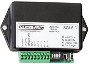 Speedometer Signal Wiring...The RX-7's speedometer originally got it's signal from a generator mounted on the driver's side of the RX-7 transmission's tailhousing. The easiest way to correct this is to use a "digital ratio adapter", such as the Dakota Digital SGI-5C, which is wired as follows...
...SGI-5C PWR...connect to RX-7 B1-01 ECU plug terminal 1B, a 12v switched power source that comes thru the RX-7's main "EGI" relay.
...SGI-5C GND...connect to salvaged emissions harness half of RX-7 X-14 connector's orange wire (wire color changes to yellow w/ white stripe on the dash harness side of X-14). This wire should also be connected to a good chassis ground such as one of the former RX-7 ECU mounting studs.
...SGI-5C SIG IN...connect to LT-1 harness C-220 connector terminal "G", a dark green w/ white stripe wire that comes from the LT-1 PCM's VSS output (PCM terminal D8).
...SGI-5C OUT...connect to salvaged emissions harness half of RX-7 X-14 connector's green wire (manual cars) or green w/ black stripe (automatic cars) (wire color changes to yellow w/ white stripe on the dash harness side of X-14). Use output 3, and set the dip switches as follows...
......dip #1- on
......dip #2- on
......dip #3- off
......dip #4- on
Tachometer Signal Wiring...The RX-7's tachometer originally got it's signal from the rotary engine's ECU. Simply connecting the V-8's tach signal to drive the RX-7 tach will result in a reading that is twice the actual LT-1 engine speed. The easiest way to correct this is to use a "digital tach adapter", such as the Dakota Digital SGI-8, which is wired as follows...
...SGI-8 PWR...connect to RX-7 B1-01 ECU plug terminal 1B, a 12v switched power source that comes thru the RX-7's main "EGI" relay.
...SGI-8 GND...connect to chassis ground at the same place as the RX-7 X-14 connector's large black wire. This wire should also be connected to a good chassis ground such as one of the former RX-7 ECU mounting studs.
...SGI-8 SIG IN...connect to LT-1 harness C-230 connector terminal "D", a white wire that comes from the LT-1 PCM's tach output
...SGI-8 OUT 1...connect to RX-7 B1-01 ECU plug terminal 2B, a yellow w/ blue stripe wire which was formerly the signal input point for the RX-7 tach.
Back-up Lite Switch...to operate the RX-7's back-up lites, Mazda used a transmission mounted SPST switch to complete the circuit.
When the RX-7's emission harness is removed with the rotary engine, part of this circuit is removed as well.
To restore this circuit, a 2 wire harness extension to the new reverse switch will need to be added from connector X-14, a rectangular 2 row 14 wire connector (1 row of 6, 1 row of 8, 2 wires missing) between the "emissions" and "dash" harness, located under the dash in the passenger footwell area. 2 of the wires in this connector are for the back-up lite switch. Wire colors for this circuit change as they pass thru X-14. If you are tapping into X-14 by salvaging the discarded male emissions harness side of X-14, these wire colors are...
...green w/ yellow stripe (manual trans) or black wire w/ yellow stripe (auto trans)...from 15a fuse in underdash fusebox.
...yellow w/ red stripe (manual trans) or brown w/ black stripe (auto trans)... goes to back-up lites.
Connecting these two wires together w/ a jumper wire will turn on the RX-7's back-up lites when the ignition switch is in the "ignition" and "start" positions.
Routing and connecting these two wires to your new transmission's back-up lite switch will enable the RX-7 back-up lites when "reverse" position of the shifter is selected.
Low Coolant Level Warning Buzzer and Lite...the warning buzzer was an absolute necessity for the rotary engine, but is generally not worth the trouble when installing a LT-1. To dis-able the annoying coolant alarm buzzer, simply ground the brown w/ white stripe wire in connector X-12.
Low Oil Level Sensor Wiring Modifications...If you have an LT-1, you may already have a low oil level sensor installed in your oil pan. Problem is, the RX-7 sensor and the LT-1 sensor work exactly opposite of each other. With the RX-7 sensor, low oil level closes a reed switch, grounding one leg of the warning lite bulb, causing it to illuminate. With the Chevy sensor, low oil level causes the ground leg to be opened. If you want to retaining this function you will need to use a relay to make the sensor compatible with the warning lite circuit.
LT1 VATS Anti-Theft System...The GM Vehicle Anti-Theft System (VATS) is not used here, but the proper enable signal must be fed into the LT-1's PCM to enable the engine's injectors to allow engine start-up. We use a "VATS Eliminator Box" that creates the proper 50hz square wave signal for the LT-1's PCM terminal A19 (dark blue wire) necessary to enable engine operation. The VATS Eliminator boxes usually have 3 wires, that need to be connected as follows...
red wire...connect to 12v hot in ign/start.
black wire...connect to ground.
green or blue wire...connect to LT1 harness C230 terminal "E" (dark blue wire).
AC System- Relay, Compressor & Pressure Switch...Only 2 circuits need modification for your AC system to function properly.
...AC relay (G-02)... in the #2 position in the relay box located in the nose of the car just to the passenger side of the hood latch. It has a square connector with 4 wires attached. It's terminals need to be re-connected as follows...
......blue w/ black stripe wire...connect this wire to one leg of the RX-7's pressure switch located near the RX-7's reciever/drier. The other leg of the pressure switch connects to "12v +" thru the "AC ON" switch.
......yellow w/ black stripe wire...connect this wire to ground.
......black w/ red stripe wire...connect this wire to the "+" side of your compressor's magnetic clutch. Connect the other leg of the magnetic clutch coil goes to ground.
......yellow wire...connect this wire to a "12v ign on" power source.
...AC pressure switch...a 2 terminal switch located next to the RX-7's reciever/drier. The switch's harness connector can be clipped from the front harness and re-used. The 2 legs of this switch/connector can re-wired as follows...
......violet wire...connect to "12v +" thru the "AC ON" switch.
......grey w/ red stripe wire...connect to the AC Relay's blue w/ black stripe terminal.
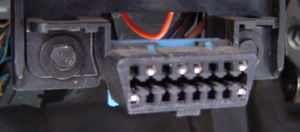 Data Link "DLC" Connector...this under-dash connector is not necessary to run your car, but it will be necessary to access the PCM's diagnostic features and will be required to pass a smog inspection. The data link connector was not part of the LT1's engine harness, but one can be easily obtained from most '93-'95 GM cars in a wrecking yard. Simply attach the DTC connector body under your RX-7's dash in an accessable but inconspicous place, then make the connections listed below. This 16 pin connector is arranged in 2 horizontal rows of eight, with the top row numbered left to right 1 thru 8, and the bottom row numbered 9 thru 16. The necessary connections are listed below...
...pin 4 (black wire)- connect to chassis ground
...pin 5 (black w/ white stripe wire)- connect to engine ground
...pin 6- connect to LT1 harness C230 connector's "C" terminal white w/ black stripe wire (field service enable)
...pin 9- connect to LT1 harness C220 connector's "F" terminal tan wire (PCM serial data)
...pin 16 (orange wire)- connect to battery "12v+" constant power source.
The rest of the DTC's connector terminals are not used.
Malfunction Indicator Lamp (MIL)...although not necessary to run your car, a working "MIL" will be required to pass a smog inspection. Your RX-7's dash display contains a "MIL" lamp, which can be controlled by the LT1 PCM by following a few simple steps...
...STEP 1-...Locate your RX-7's "electrical load control unit" (ELU), located in the passenger kick panel area in front of the passenger side door hinges.
...STEP 2-...Unplug RX-7 connector B1-20 from the ELU. B1-20 is a rectangular black 16 pin connector (2 rows of 8), with only 8 wires and 8 empty slots. Wire colors are...
............black...
............orange w/ black stripe...(grounding this wire will illuminate RX-7's MIL lamp)
............orange w/ blue stripe...
............black w/ white stripe...
............white...
............white w/ black stripe...
............tan...
............grey...
...STEP 3-...The ELU itself is no longer needed, and can now be removed and discarded (it's former function was to increase the rotary engine's idle speed when certain electrical accessories were activated).
...STEP 4-...connect RX-7 connector B1-20 pin "K" (orange w/ black stripe wire) to LT1 connector C-230 pin "B" (brown w/ white stripe wire). The other 7 wires in RX-7 connector B1-20 are no longer used.
This guide will help you locate and identify the RX-7 harness connectors for required connections and modifications...
 ...X-1 Main Fuse Block...is the power distribution and fusible link block that was formerly located on the positive terminal of the RX-7's stock battery.
...X-02 Relay and Fuse Block...is the fuse and relay box that is located on the driver's side shock tower that contains the fuel pump relay, EGI main relay, and fuses for the AC, ABS, defroster, and cooling fans.
...X-05 Connector...is a blue connector located in the passenger footwell area. The actual connector size is different depending on if the RX-7 was originally equipped with a manual trans or an automatic trans.
............manual trans...12 pin connector
............automatic trans...22 pin connector
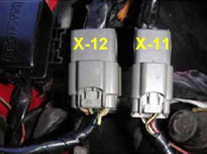
...X-11 Connector (location pictured on right)...is a grey 4 pin connector located in front of the driver's side shock tower.
...X-12 Connector (location pictured on right)...is a grey 12 pin connector located in front of the driver's side shock tower.
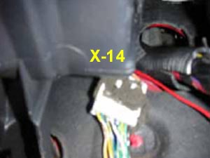 ...X-14 Connector (location pictured on right)...is a white 14 pin (manual trans) or 18 pin (auto trans) connector located under the dash behind the blower motor, behind the glove box, near where the harness passes thru the RX-7 firewall on the passenger side. The female side of X-14 is attached to the dash harness. The male side is is attached to the emissions harness, and is removed with the rotary engine ECU. We suggest that you retain the male emissions half of X-14, along with a section of connected wires, as an easy way to access X-14 without having to work upside down under the dash. Be warned that several wires change color as they pass thru X-14, which can cause confusion, and that wire colors and wire locations within the connector are different depending on if your RX-7 was originally equipped a manual or automatic transmission.
...B1-01 ECU Connector...is a 22 pin connector that plugged into the rotary engine's ECU that was located on the passenger side behind the kick panel
...B1-02 EGI Main Relay Connector...is located under the EGI Main Relay in the Relay and Fuse Block located on the RX-7's driver's side shock tower.
...B1-03 Circuit Opening Relay Connector...the Circuit Opening Relay is inside the Relay and Fuse Block, located behind the battery in front of the RX-7's driver's side shock tower. It's the large green relay labeled "EFI". This is also functions as the main fuel pump relay.
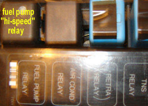 ...B1-04 Fuel Pump "hi-speed" Relay Connector...is located inside the plastic box in front of the radiator on the passenger side, near the right headlite.
...B1-05 Fuel Pump Resistor Connector...located under the brake master cylinder, looks like a finned aluminum box w/ 2 wire connector going to it...
......blue w/ red stripe...
......white w/ red stripe...
2....Considerations & Requirements....
4....Engine / Transmission Installation....
5....Exhaust / Throttle Cable / Accessory Drive / Pulleys....
6....Cooling / Fuel Systems....
7....RX-7 Wiring Harness Connector ID and Circuit Locations....
8....Electrical System Modifications By Circuit....
9....Start-up / Troubleshooting....