
ClutchTamer Universal/Musclecar Install Guide...
ClutchTamer Universal/Musclecar Install Guide...
Pre-Installation Requirements...
Step 1- Installing the Clutch Pedal Bracket...
IMPORTANT- you must have an effective clutch pedal stop in place BEFORE you install the ClutchTamer! A very important part of getting consistent launches is to have in place a properly adjusted clutch pedal stop. It's function is to insure that the slipper's rod is always pulled out exactly the same amount every time the car is staged, so that it can consistently delay the clutch's lockup.
NOTE-...if you are performing a custom installation, be sure to orient the cylinder with the shaft end (with delay knob) HIGHER than the cylinder end. This is to insure that the oil in the cylinder is self bleeding, as to keep any air pockets away from the internal metering circuit.
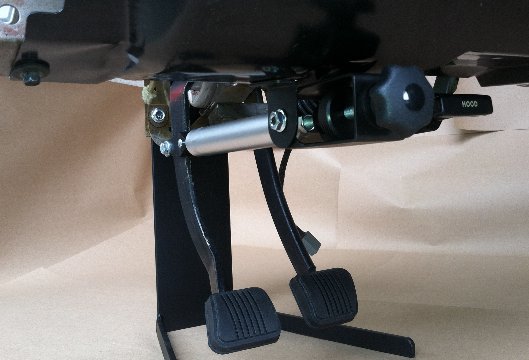
Our universal single tab clutch pedal brackets are designed to install by simply drilling a small hole in the arm section of the pedal. For mock-up purposes, the tab should be temporarily secured to the pedal with a small clamp until the proper stroke length is determined. Moving the pedal bracket up or down on the pedal will effectively alter the cylinder stroke length. More stroke is better than less, but 3" is the maximum. Stroke lengths longer than 3" could cause the cylinder to top out, and could damage the cylinder's seal.
NOTE- Also be sure to check for interference above the cylinder as the pedal swings thru it's arc, as the cylinder can be damaged if it comes in contact with a bracket or something structural. Temporarily securing the bracket with a small clamp will make it easy to change it's position until it's ideal position can be determined.
Step 2- Install the ClutchTamer's Hydraulic Cylinder onto the Clutch Pedal...
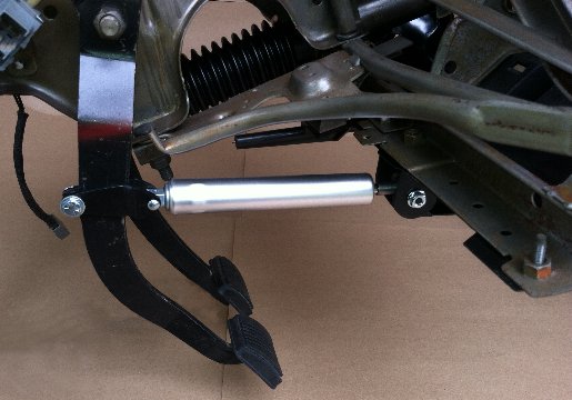
Place the hydraulic cylinder into position under the dash, and secure it to the clutch pedal bracket with the provided attachment pin and retaining clip. Do not install the threaded rod onto the cylinder's shaft at this point.
Step 3- Fitting the Dash Slide Bracket to the Dash Substructure...
NOTE- if you need to remove the plastic slide bushing from the dash bracket, it just "snaps" together. Simply slip a small blade under the rear "washer" portion, with a gentle pry it should snap free from the slide bushing. A small set of pliers can be used to "snap" the washer/bushing back together for re-install.
We provide a simple universal dash bracket that is made of mild steel. It has the basic shape that is needed in the center for the cylinder's shaft to pass thru, but the ends of the bracket that actually attach to the dash may require some minor fabrication to make them fit up properly to your existing dash substructure. Since the material is mild steel, it can easily be bent or hammered at it's ends to achieve a perfect fit. The proper orientation should have the slide bushing in the middle of the bracket perpendicular to the shaft that passes thru it, so that the knob and dial will contact the bushing's face evenly top/bottom/side/side. After you are satisfied with the Dash Bracket's fitment, remove it and place it aside while you further prepare the area for it's final attachment.
Step 4- Attaching the Dash Slide Bracket to the Dash Substructure...
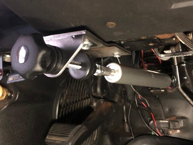
For final attachment, we like to spot weld the bracket to the substructure. As an alternative rivets or small bolts/nuts could also be used. If spot welding, be sure to take proper precautions to prevent fire and/or damage to electronic equipment. Below is shown a universal underdash installation...
Step 5- Trimming the Length of the Threaded Rod...
...re-install the threaded rod thru the slide bushing and into the cylinder's rod. Bottom it out in the coupler's threads, then secure it in place with the provided jam nut.
...screw the plastic Delay Knob onto the threaded rod until it's threads bottom out, then just slightly more until it is tight enough so that the Delay Knob can be used for turning the cylinder's shaft. At this point, the Delay Knob should seem to be sticking out way too far.
...rotate the Delay Knob counter-clockwise until you can feel the added resistance to rotation when it reaches the end of it's adjustment range. This point is what we call it's "0 Turns" adjustment.
...turn the Delay Knob clockwise to the "2 Turns" adjustment position, then measure the distance between the Dash Bracket's Slide Bushing and the flat area on the Delay Knob. Write down this measurement, this will be the "cut amount" that will be trimmed from the long end of the threaded rod.
...remove the plastic Delay Knob from the threaded rod.
...remove the threaded rod from the cylinder's shaft.
...note that the threaded rod has a groove milled into it appx 1" from one end. DO NOT cut this end of the threaded rod, we call this end the "short" end. Trim the "cut amount" from the "long" end of the threaded rod, take care not to damage the rod's threads.
Ideally, when finished trimming the rod's length, you will end up with a "Delay Gap" that's about 1 thread wide when adjusted to "0 Turns", just like the gap located in the center of the picture below...

Step 6- Assembling the threaded shaft, "Initial Hit Dial", and "Lockup Delay Knob" onto the cylinder...
...remove the cylinder from the clutch pedal bracket
...thread the "long end" of the threaded rod into the cylinder's shaft, then secure it in place with the jam nut.
...thread the "Initial Hit Dial" onto the "short end" of the threaded rod until appx 1-1/4" of the threaded rod sticks out of the flat face of the dial.
...re-install the cylinder/rod assy thru the hole in the dash substructure and thru the Dash Bracket's Slide Bushing.
...re-install the cylinder onto the clutch pedal bracket.
...thread the plastic "Lockup Delay Knob" onto the threaded rod. Tighten it slightly until there is just enough resistance to reliably adjust the "Lockup Delay Knob" without it un-screwing from the threaded rod. With the "Lockup Delay Knob" installed, there should be a small gap between the "Lockup Delay Knob" and the "Slide Bushing" when the Delay is adjusted to "0 Turns".
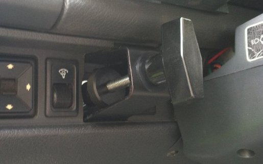
Below is a pic of a Musclecar dash bracket mated to an owner fabricated adapter bracket. Not wanting to drill any extra holes in his nice original car, this owner made an adapter bracket from flat 1/8" thick steel plate that attached to existing holes in his dash substructure...
Step 7- Trimming the Lower Dash's Plastic Cover Panel...
Step 8- Initial Setup & Tuning...
...CLICK HERE to go to our "initial setup & tuning guide