
'94-2004 SN95 Mustang ClutchTamer Install Guide...
'94-2004 SN95 Mustang ClutchTamer Install Guide...
Pre-Installation Requirements...
IMPORTANT- you must have a clutch pedal stop in place! A very important part of getting consistent launches is to have in place a properly adjusted clutch pedal stop. It's function is to insure that the slipper's rod is always pulled out exactly the same amount every time the car is staged, so that it can consistently delay the clutch's lockup.
Step 1- Installing the Clutch Pedal Bracket...
Step 2- Install the ClutchTamer's Hydraulic Cylinder onto the Clutch Pedal...
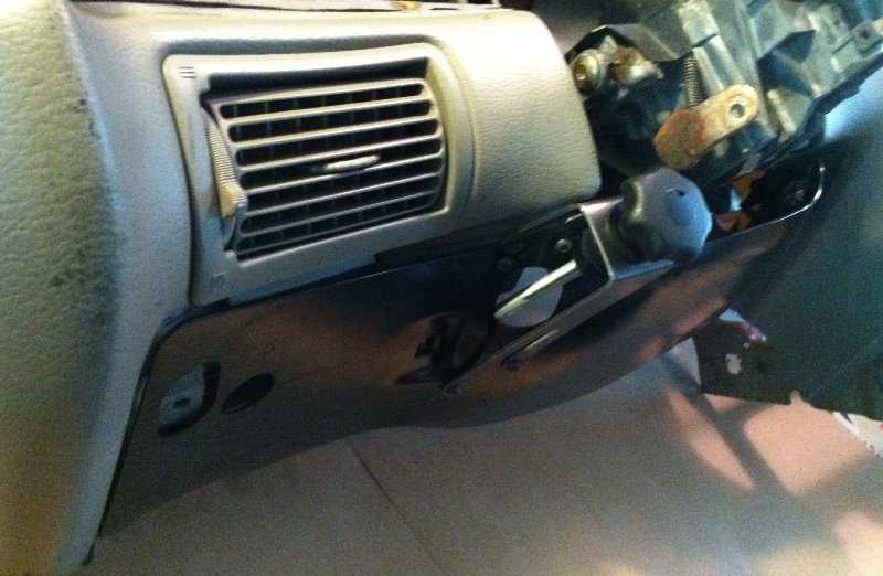
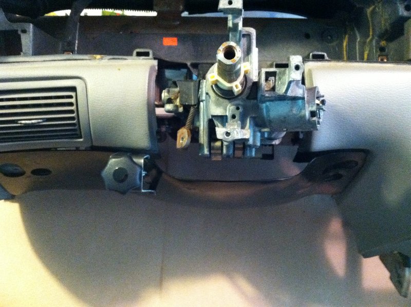
Step 3- Preparing the Dash for Slide Bracket installation...
Our clutch pedal brackets are designed to install by simply slipping them over your pedal's "arm", secured to the pedal by a simple pinch bolt. This allows you to easily slide the bracket up/down the pedal for proper positioning. Properly installed, the cylinder attachment point on the bracket should be offset to the brake pedal side of the clutch pedal, this offset is necessary in order for the cylinder to clear the SN95's fusebox. Place the upper edge of the pedal bracket appx 1-1/2" to 2"" below the welded tab on the clutch pedal's arm, then tighten the pinch bolts to secure the bracket's position.
NOTE- Be sure to double check for clearance above the cylinder as the pedal swings thru it's arc, as the cylinder can be damaged if it comes in contact with a bracket or something structural.
Place the hydraulic cylinder into position under the dash, and secure it to the clutch pedal bracket with the provided attachment pin and retaining clip. Do not install the threaded rod onto the cylinder's shaft at this point, simply let the cylinder hang down.
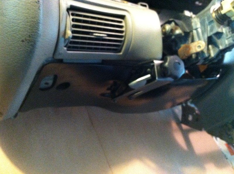
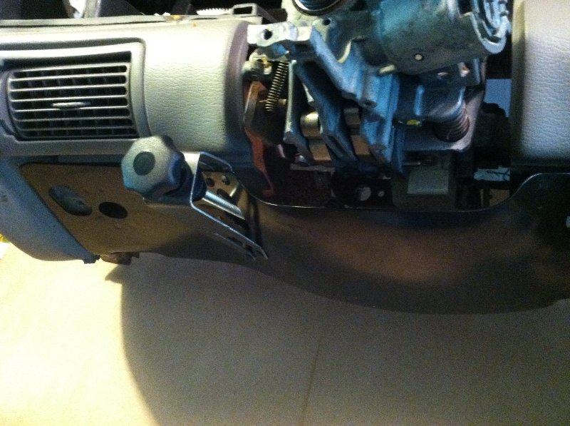
...using an 8mm socket, remove the two bolts located in the two lower corners of the plastic trim panel, located below the steering column. Pop the remaining two upper retaining clips loose to gain access to the removable black metal "knee bolster" panel.
...again using the 8mm socket, now remove the two remaining upper bolts, then remove the metal knee bolster panel.
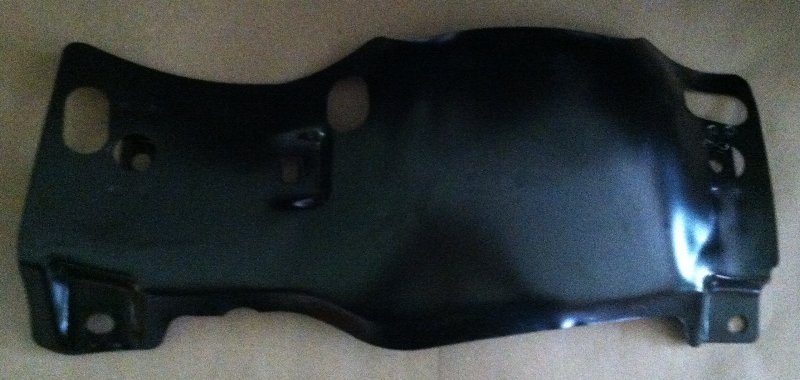
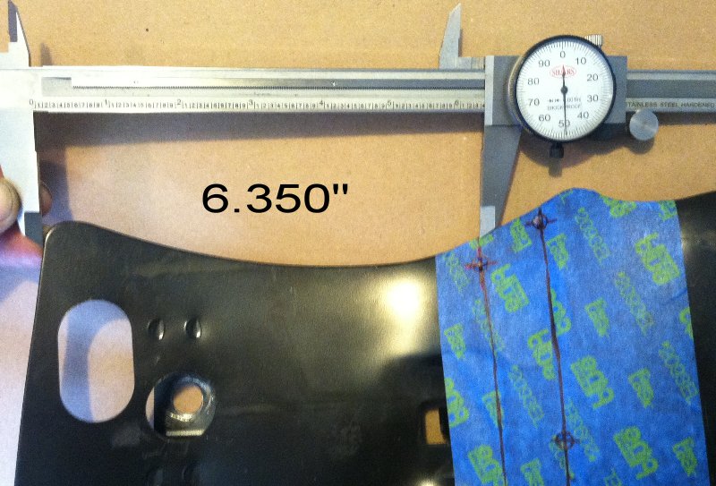
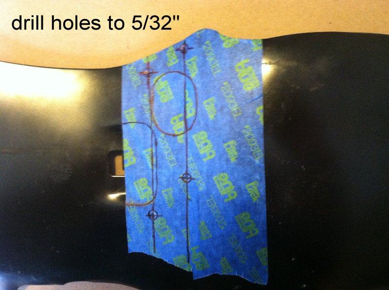
Apply a couple strips of masking tape to the panel in the area shown, it will make laying out the drill pattern much easier...
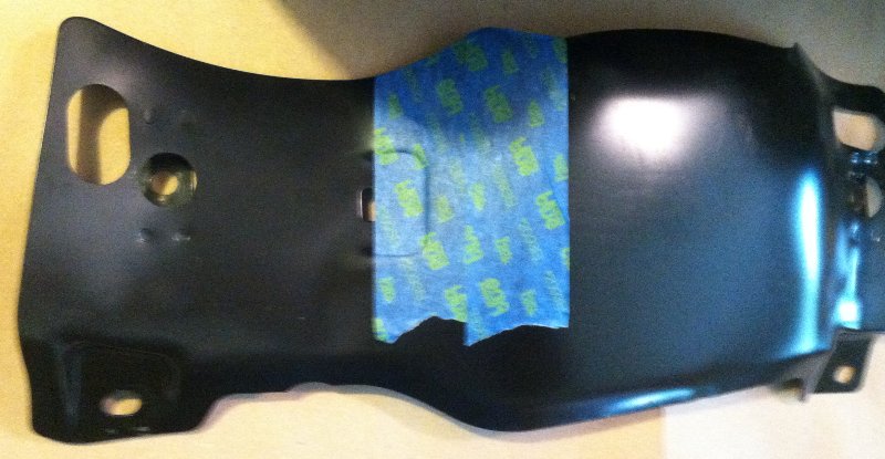
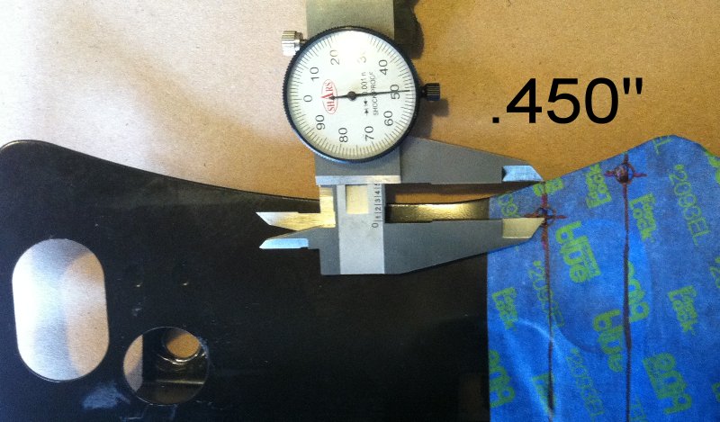
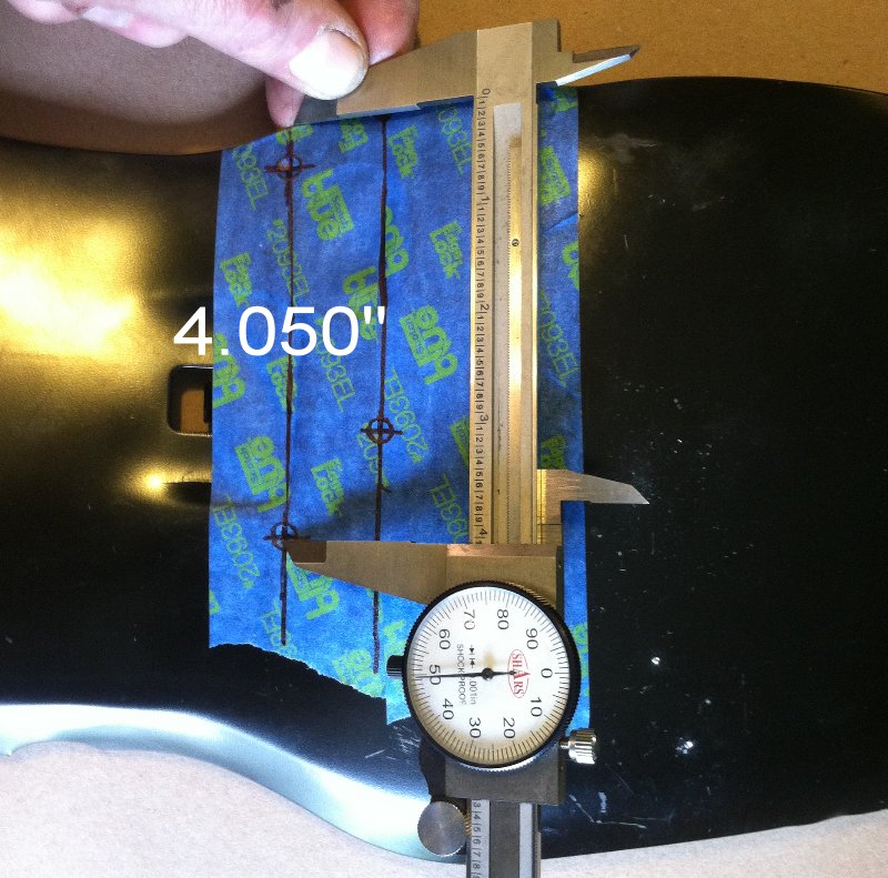
The first step in drawing the drill pattern is to draw a couple of vertical lines. Place a mark 6.350" from the upper edge of the panel...
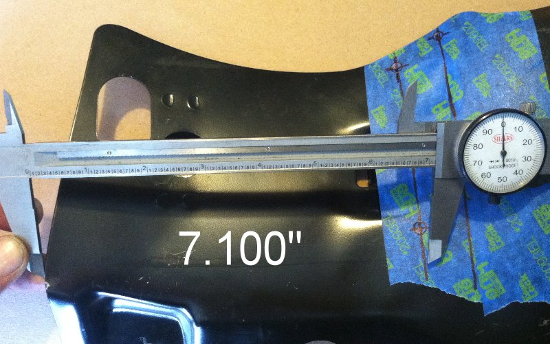
Place another mark 7.100" from the lower edge of the panel...
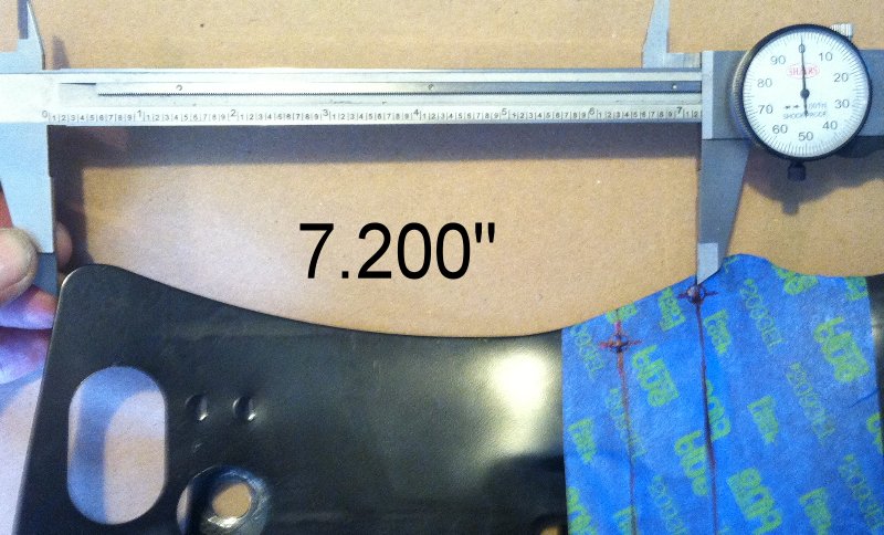
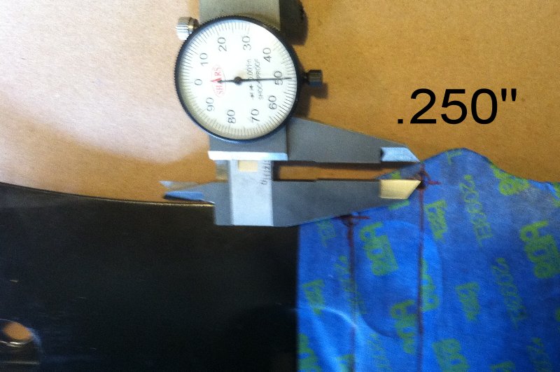
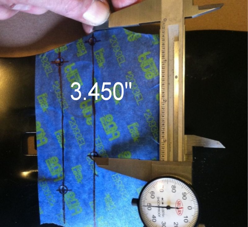
Place another mark 7.200" from the upper edge of the panel...
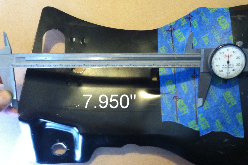
Place another mark 7.950" from the lower edge of the panel...
Next, using a flexible straight edge (strip of poster board will work), draw two vertical lines thru the marks. After the vertical lines are drawn, measure from the top edge of the panel to locate the centers of the four holes that will be used to attach the ClutchTamer's dash bracket...
After drilling the holes, remove the masking tape and attach the dash bracket to the steel panel. The upper ears of the dash bracket fit over the top of the panel, and attach to the back side. The bracket's lower ears attach to the face of the panel as shown...
Re-install the steel panel on the dash structure...
...re-install the metal knee bolster panel onto the dash.
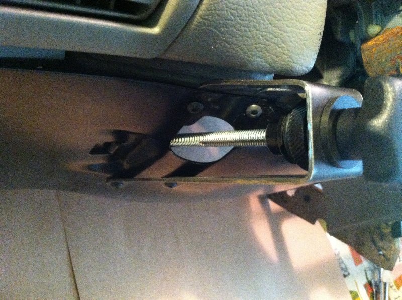
...insert the 5/16" threaded rod thru the new holes and screw it into the end of the hydraulic cylinder's shaft. The threaded rod should now stick out quite a bit from the dash, but do not cut it's length yet. The cylinder and threaded rod should now be very close to their installed position.
Step 4- Trimming the Length of the Threaded Rod...
...re-install the threaded rod thru the slide bushing and into the cylinder's rod. Bottom it out in the coupler's threads, then secure it in place with the provided jam nut.
...screw the plastic Delay Knob onto the threaded rod until it's threads bottom out, then just slightly more until it is tight enough so that the Delay Knob can be used for turning the cylinder's shaft. At this point, the Delay Knob should seem to be sticking out way too far.
...rotate the Delay Knob counter-clockwise until you can feel the added resistance to rotation when it reaches the end of it's adjustment range. This point is what we call it's "0 Turns" adjustment.
...turn the Delay Knob clockwise to the "2 Turns" adjustment position, then measure the distance between the Dash Bracket's Slide Bushing and the flat area on the Delay Knob. Write down this measurement, this will be the "cut amount" that will be trimmed from the long end of the threaded rod.
...remove the plastic Delay Knob from the threaded rod.
...remove the threaded rod from the cylinder's shaft.
...note that the threaded rod has a groove milled into it appx 1" from one end. DO NOT cut this end of the threaded rod, we call this end the "short" end. Trim the "cut amount" from the "long" end of the threaded rod, take care not to damage the rod's threads.
Ideally, when finished trimming the rod's length, you will end up with a "Delay Gap" that's about 1 thread wide when adjusted to "0 Turns", just like the gap located in the center of the picture below...

Step 5- Assembling the threaded shaft, "Initial Hit Dial", and "Lockup Delay Knob" onto the cylinder...
...remove the cylinder from the clutch pedal bracket
...thread the "long end" of the threaded rod into the cylinder's shaft, then secure it in place with the jam nut.
...thread the "Initial Hit Dial" onto the "short end" of the threaded rod until appx 1-1/4" of the threaded rod sticks out of the flat face of the dial.
...re-install the cylinder/rod assy thru the hole in the dash substructure and thru the Dash Bracket's Slide Bushing.
...re-install the cylinder onto the clutch pedal bracket.
...thread the plastic "Lockup Delay Knob" onto the threaded rod. Tighten it slightly until there is just enough resistance to reliably adjust the "Lockup Delay Knob" without it un-screwing from the threaded rod. With the "Lockup Delay Knob" installed, there should be a small gap between the "Lockup Delay Knob" and the "Slide Bushing" when the Delay is adjusted to "0 Turns".
Step 6- Trimming the Lower Dash's Plastic Cover Panel...
You may choose to leave the plastic trim panel off, but it can be trimmed and re-installed without much trouble. Trimming the panel will remove one of it's attaching clips, a couple Velcro strips can be used on the backside of the trim panel to take the place of the missing clip. If you are apprehensive about trimming your original plastic trim panel, you can source one for $20 or so from the wrecking yard or ebay to be trimmed. That way you will still have your pristine original panel should you ever decide to remove the ClutchTamer to sell the car.
Step 10- Initial Setup & Tuning...
...CLICK HERE to go to our "initial setup & tuning guide
If you have any questions, feel free to e-mail me