Little Motor, Little Tires, Little Nitrous...
The Granny's Speed Shop "Shop Mule"
(scroll down for the bellhousing fabrication project)

This car was actually the second RX-7 to get a V8 in my shop. The first was a white '79 from California, it was found abandoned near a bar in Alger, WA.
The '79 proved too hard to get a title for, so we switched the SBC/T5/8.5 10 bolt drivetrain originally built for the '79 into this '85 GS body. That was about 30 years ago..
Shit happens when you occasionally get bored with a car over the course of 30 years!
Here's some build pics of the Shop Mule as it suffered it's "setback" back in 2010...
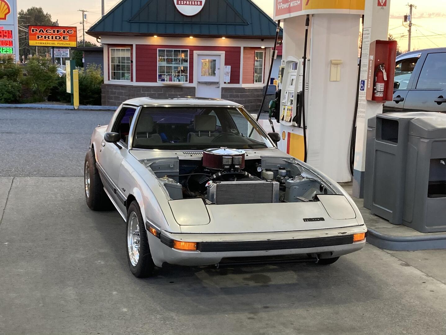
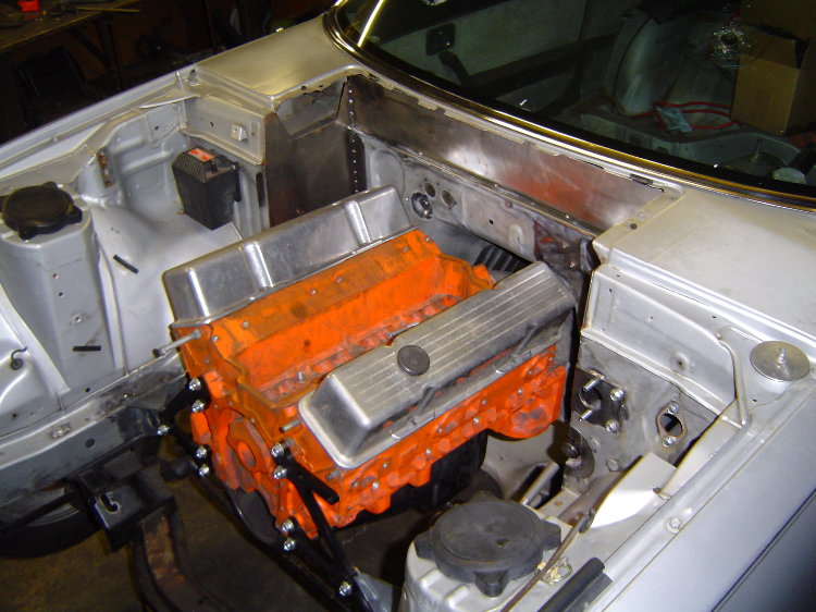
...a 10" engine / radiator setback combined with a 7" dash and 6" seat rail setback. My goal for this little project was to be able to remove 100 lbs of rear bumper ballast and still be able to hook the tires on airport runways and such. It may look like radical surgery, but it's not that hard...I used a Sawzall and a MIG welder. Even after the engine setback modifications, the body still looks stock from the outside.
Basically, I moved the engine back as far as possible, while still being able to wiggle it's distributor past the base of the windshield. The cowl panel goes back on, but is easily removable when the hood is up.
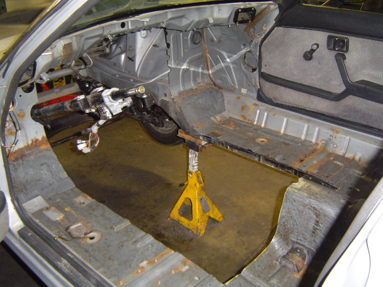
These RX-7 transmission tunnels are HUGE! That's because the RX-7 was designed for a rotary engine, which has it's "crankshaft" up in the middle of the engine instead of down in the bottom like the typical piston engine. Because of this, the rotary engine's transmission sits a lot higher, which in-turn requires a much bigger trans tunnel. Basically the entire center portion of the stock floor pan and firewall were cut out, 9-1/2" cut off the back, and welded back in. The stock seat brackets were then moved back 6", the original molded carpet still fits with slight alterations. The end result is the shifter is now closer to the driver and has perfect ergonomics for an H-pattern shifter. The offset makes the driver's push into 3rd gear a straight-line effort, also easy to reach 3rd while being pressed back in the seat. No need for a bigger/heavier in-line vertical gate style shifter.
The seal panels along the sides were made from 18ga cold rolled steel sheet. The stock firewall sheetmetal is still there, just moved back a bit in the center for "valve cover clearance" (some rules allow firewall mods for valve cover clearance). The stock RX-7 pedal assembly was spaced back away from the firewall using 7" long aluminum spacers and uses extended pushrods. I made a tunnel for the steering column, then added 7" including universal joint to the steering shaft itself. The steering shaft retains it's collapsible feature.
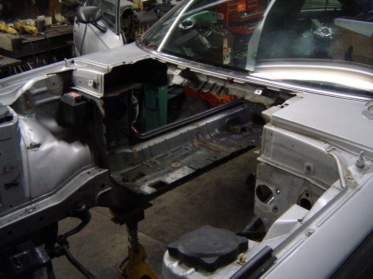
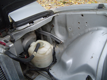
Moving the engine back now reveals the RX-7's ugly stock front crossmember. Since the crossmember no longer supports the engine, I made a lighter weight tubular version that is much more appealing, and now doubles as a radiator mount...
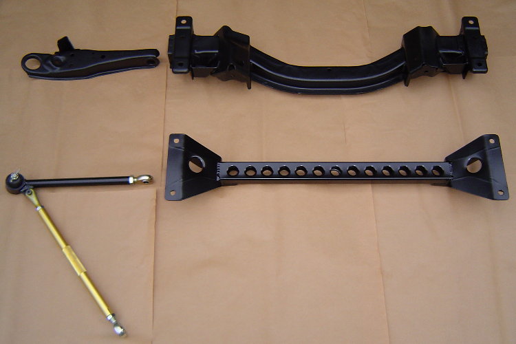
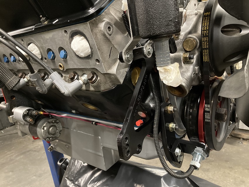
The engine now sits entirely behind the front axle. The front motor plates are from a 410 Sprint Car, and I added bellhousing mounts at the rear to make transmission maintenance easier. Inside the top of the strut towers you can see the aluminum spacers I made to increase the front suspension travel. The upper spring seats are threaded and adjustable, and the front struts have been taken apart and re-valved. The lower control arms have been lengthened 3/4" per side to correct the front camber at this car's higher ride height.
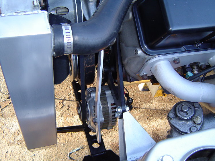
Even the radiator got moved back. The alternator was moved below the motor plate, just above the front suspension's new crossmember. Here's the steering u-joint that was added, it's from a 2nd gen RX-7...
I used an RX-7 alternator, made brackets to mount it below the motor plate.
For the rear, I decided to use a set of 275/60-15 M/T radials on a set of beadlocked Weld 15x12 wide-5 wheels with 5" of backspace...

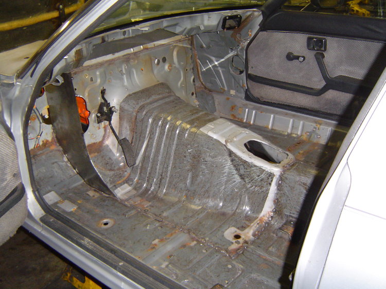
After spending a couple of months deciding just how much I wanted the rear tires to stick out of the radiused rear fenders, I decided a 1-3/8" mini-tub would give me enough inner sidewall clearance to allow plenty of articulation without rubbing. Step 1- I cut out the stock wheel tubs...

Here's a shot of a stock wheel tub being mocked back in-place after adding a 1-1/2" wide strip of 16ga to its outer radius...

On the floor, you can see the modified Crown Vic 8.8 housing. It was narrowed and 9" ends installed, housing width is 46.5". With a 2.50" brake offset, axle flange / axle flange width is 51-1/2". You can also see the torque arm I fabricated, the nose anchors up in the trans tunnel with a shackle arrangement. The driveshaft passes between the shackles, they double as a forward driveline loop. The bracket on the right axle tube is the pivot for the watts linkage that centers the rear in the car. Same torque arm that was on the 8.5" 10 bolt that got bent in the crash, just modified it to fit the 8.8. Easy 1.30 60's with this setup...

Here's the bare 8.8 with brackets and mocked in-place, necessary to determine where and how tall the new bump-stop brackets needed to be....

Here you can see the new bump stop brackets welded to the underside of the frame rails You can also see where I notched the stock sheetmetal "frame rails" to make room for the coil-overs...

I'm a big fan of the movie Two Lane Blacktop. After this car's crash in 2023, I decided to radius the rear wheelwells like the '55 in the movie so it could sit lower. Here's a shot with the rear on the bump stops...

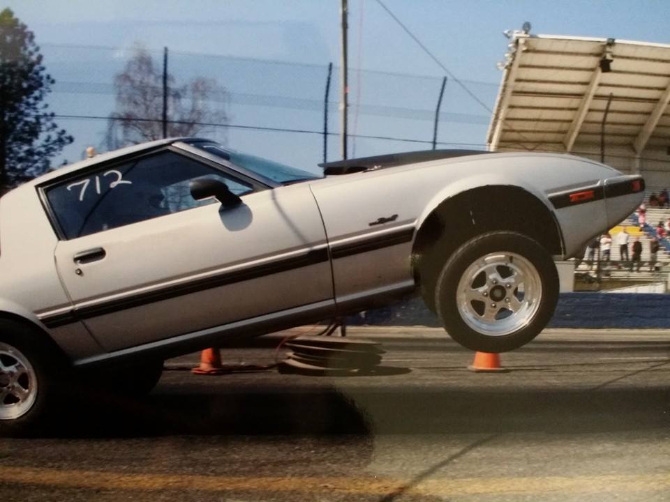
I'm also a fan of rear travel, here's a shot at full extension! Plenty of front and rear suspension travel for those un-prep'd Mexican backroads...

The shocks are non-adjustable, but there are many off-the-shelf valving combinations available. These have 4/6 valving, I also have a set of 3/5. With plenty of travel and a soft clutch hit, this car doesn't need stiff shocks to hook up...

These are stock un-modified springs from the rear of a '86-'91 RX-7, rate is 98lbs/in. The inside dia is larger than the typical 2-1/2"id coil-over spring, so I machined some spring adapters from a 4-1/2" dia chunk of Delrin. With the larger dia springs, I shouldn't have to worry about the springs rubbing on the coil-over sleeves...

Here you can see that I made the spring base as wide as possible. I could have easily put the shocks on the inside of the frame rails, but that narrow spring base would have required a very stiff sway bar. Narrow spring base, a spool, and very stiff ARB's are the reason you see cars at the strip crash into the wall. With a wide spring base, a TruTrac diff, and some articulation available, this car is far easier to control when it gets out of shape...

I went with round rotors this time, never liked the pulsing feel I got from the earlier scalloped rotors...

All done and on the road! Front tires are Firestone 135-15 on 3-1/2" wide Weld Prostars...

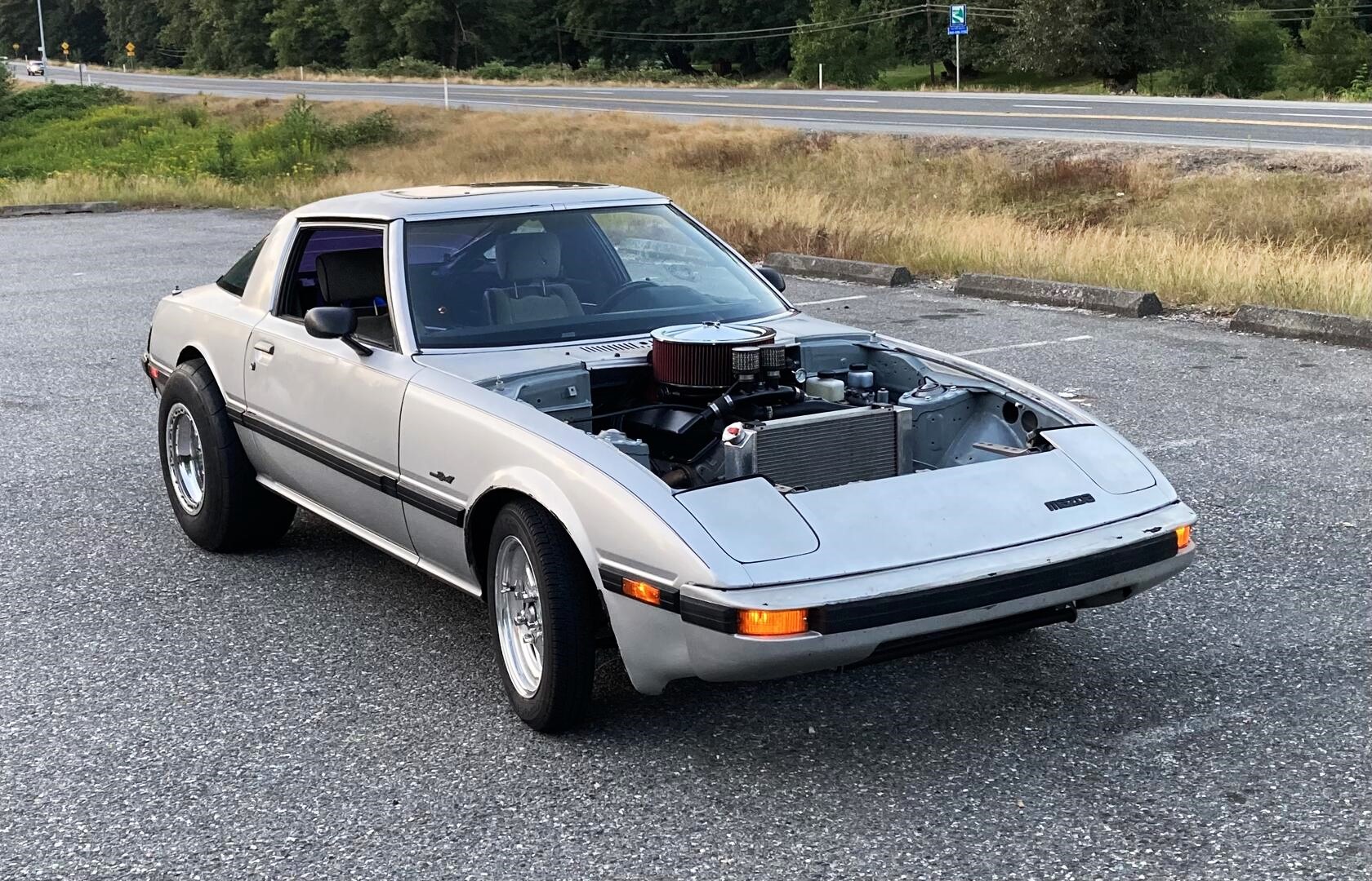
As you can see, I chose to leave the body damage as a reminder of what could have happened...

The car now weighs 2325lbs (2525lbs including a 200lb driver), about 335lbs lighter than before the setback, even though it still has original glass, stock seats, a full exhaust system and the Huge Magneflow muffler. Depending on fuel load and rear bumper weight, distribution varies between 47/53 and 43/57. Remember, this car was built for the street, not a sticky prep'd track
The ignition boxs and coil are now inside the car, behind the firewall. The new radiator mounting could not get much simpler or lighter, possible because now the engine is mounted directly to the chassis (no rubber). I may build a carbon fiber duct between the radiator and nose, but it runs cool just like this. Even in 98 degree heat, it still idles at 185 degrees.
Here's a pic of the outside of the car, just a hotrod built for fun on the street...and a random test-n-tune or grudge night here and there.
Still need to add power windows, as the setback dash now covers the window cranks (the doors must be opened to roll the windows up/down). With the exception of the firewall, trans tunnel, mini tub mods, the car pictured here has a completely stock body- no subframe connectors, no roll bar, and no added chassis reinforcements. Even the hangers for the exhaust system were made to use existing holes in the chassis.
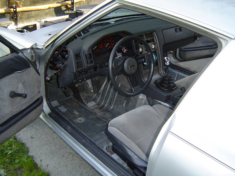
I still need to make some extension panels to cover the area between the cowl and dash. The little black knob ahead of the driver's door opening is the adjustable prop valve for the rear brakes.
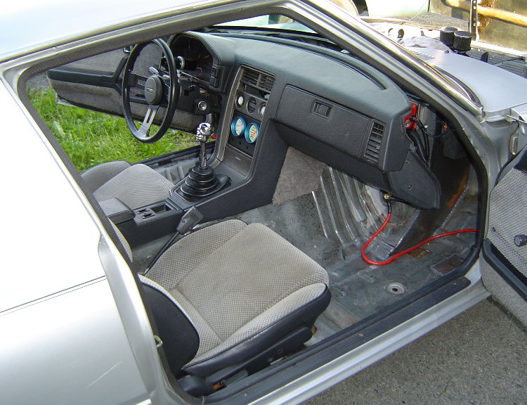
A gauge panel was made to fill the area where the stock stereo used to reside. It's attached to the support structure under the dash, so when the dash cover is removed, the gauges stay connected and in place.
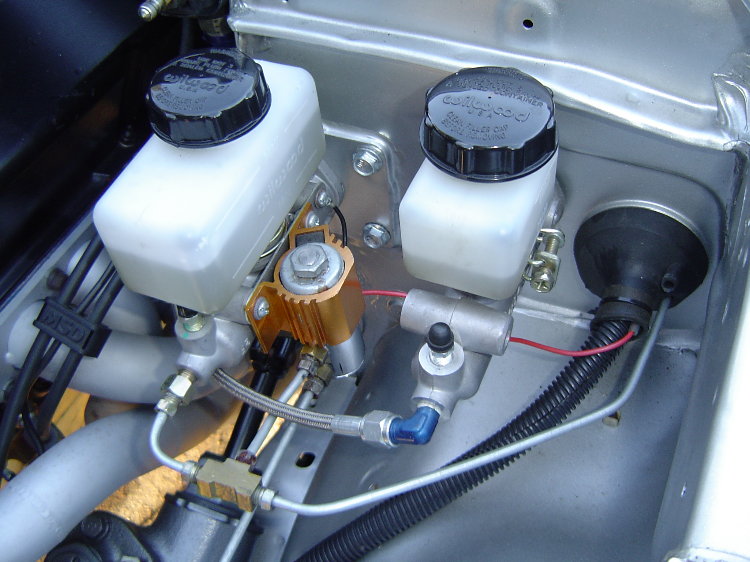
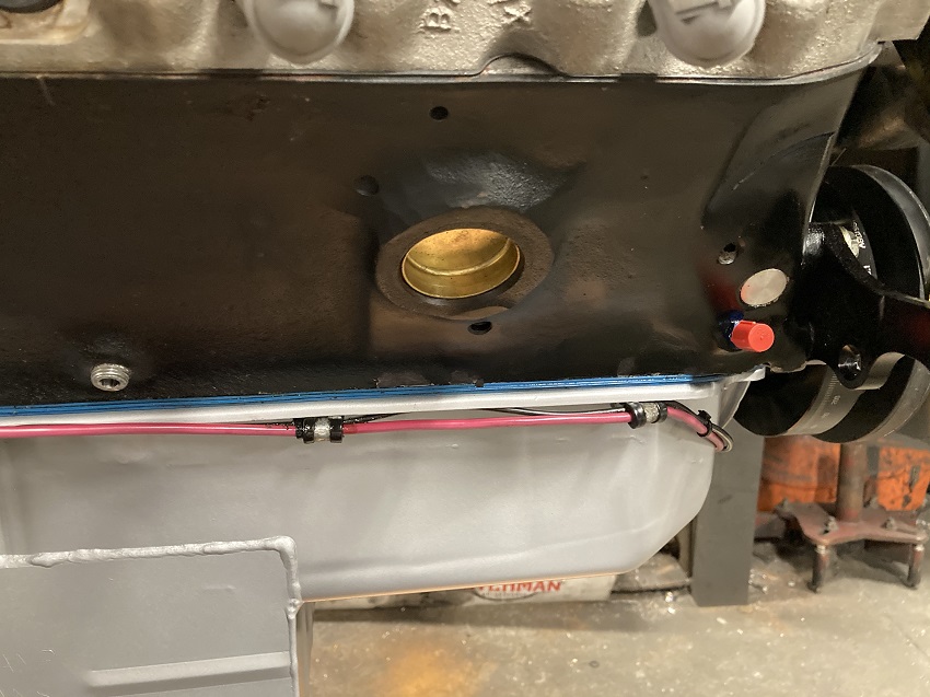
BELOW- A 7/8" brake master cyl plumbed to a lineloc and a 13/16" clutch master for the hyd t-bearing.
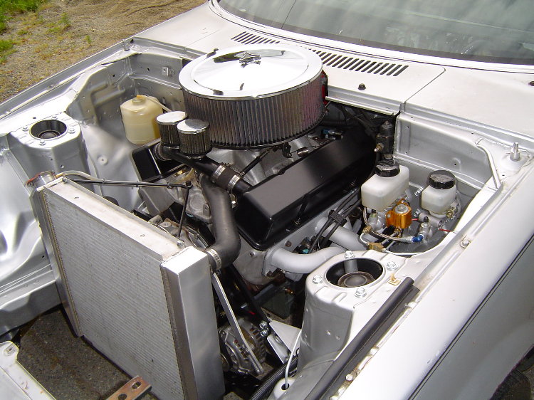
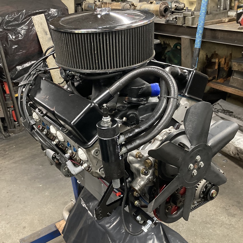
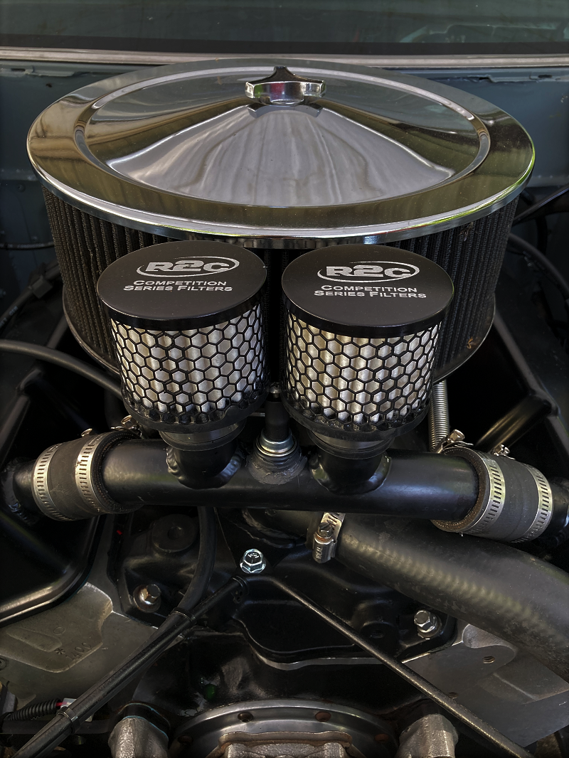
All together the current engine looks pretty innocent, doesn't really sound very wild either with low compression, 114 degree LSA, and a full exhaust system. Just a little pump gas 355 that drives thru the gate, then gets 20mpg on the way back home. Those small chunks you see stuck to the air cleaner element are actually chunks of Skagit Speedway clay, as I ran this air cleaner on my Outlaw Dirt Latemodel back in the 90's. Even though I clean this element occasionally, I take care to disturb that clay as little as possible. Here the engine is after being taken out for winter 2020 maintenance...
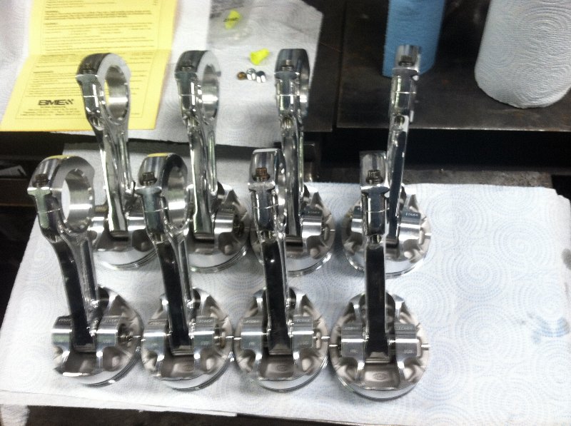
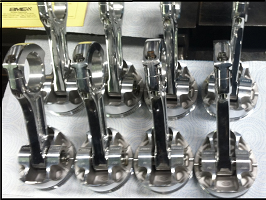
Built for spraying 500hp worth of nitrous on top of 92 octane pump gas, the 355 got forged flat tops w/ lateral gas ports and low tension gapless rings, piston-to-head clearance is set at a nitrous friendly .090" by a set of Bill Miller aluminum rods...
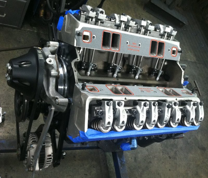
On top is a custom set of rolled Brodix -11R raised runners ported by Jones Engineering, with 2.125" titanium valves/retainers and Jesel shaft rockers. The castings were rolled (angle cut) before the headbolt holes were drilled, eliminating the need to slot holes and correct spotface angles. A set of .375" thick spacers were required for the top of the block, as the intake manifold has to sit quite a bit higher to match up with the raised intake runners. Plenty of air for a little 355, exhaust ports are raised as well...
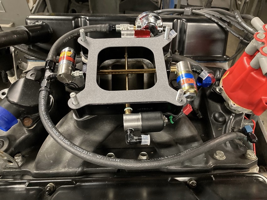
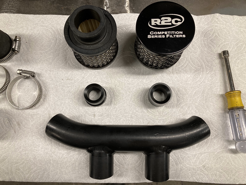
Current setup is a re-worked Holley Strip Dominator intake with a modified NOS Crosshair nitrous plate under the carb. I modified this air cleaner's original drop base by adding a 3" section, now it almost completely hides the 2 stage nitrous system...
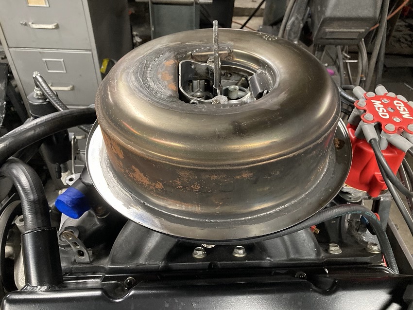
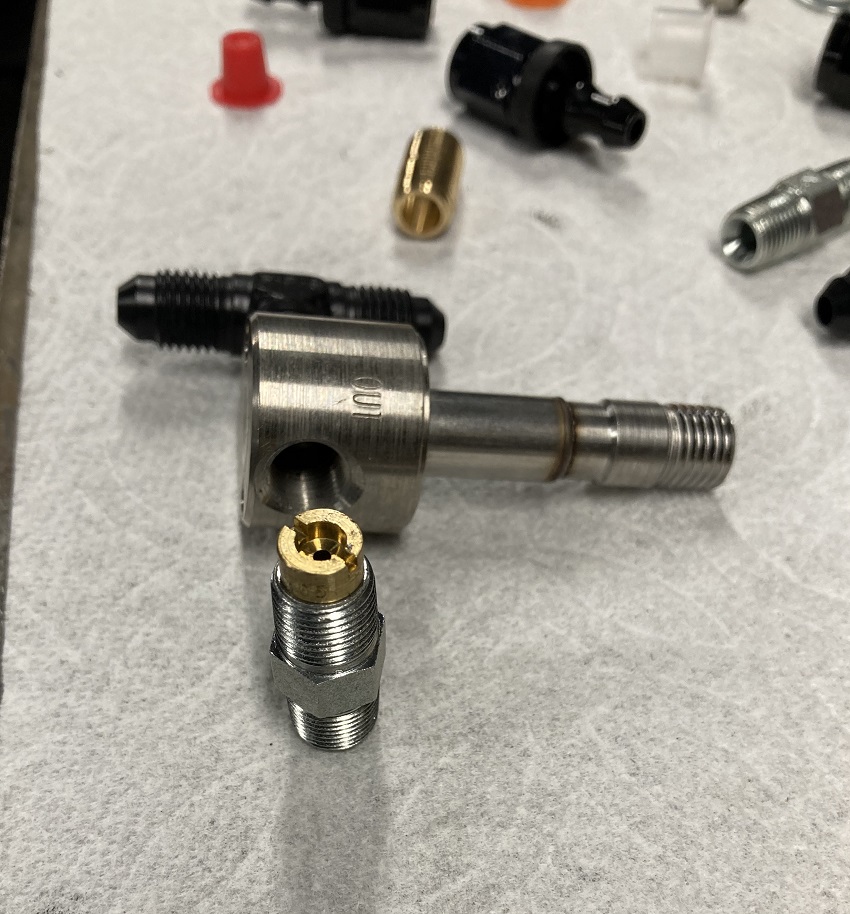
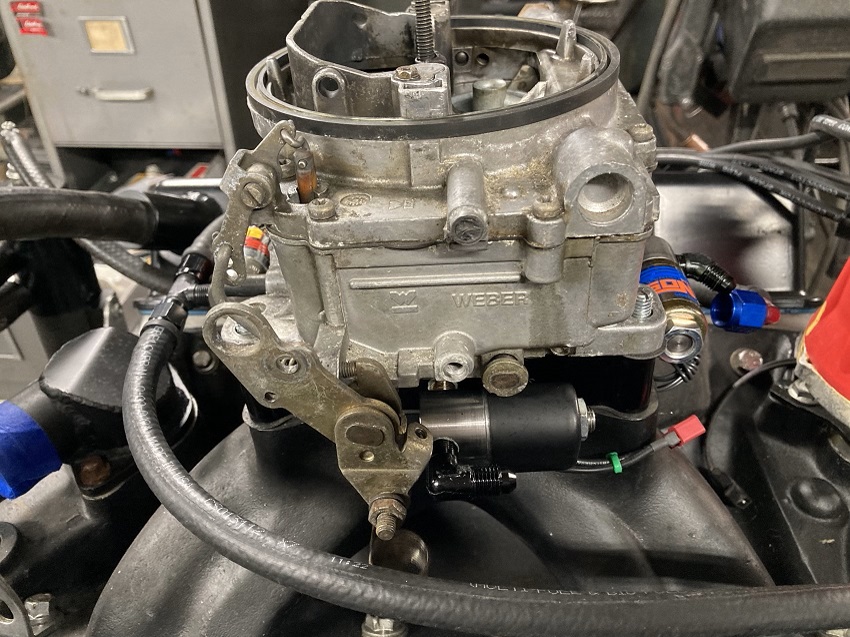
Blows people's minds when I pull the top of the air cleaner off to "change the metering rods". This little 625cfm Edelbrock/Weber makes it easy to underestimate the car's true potential, but in the end carb size doesn't really matter as much when a large percentage of the overall mixture ends up coming in below it's throttle blades. Solenoids for the N2O system are mounted directly to the plate, under the carb and mostly hidden behind the air cleaner base. On the fuel side of the nitrous system, Holley jets are pressed into the steel nipples between the fuel solenoids and the plate. On the nitrous side there's no jets at all, basically flowing as much nitrous as we can get thru the solenoids. Everybody seems to know those small body Powershot solenoids only flow enough to support a 175 shot, but these solenoid's orifices has been bored out and the body hand ported. Enough jet area to flow well over 450hp worth of spray. Could have easily went to larger solenoids and accomplished the same thing, but this has become more of a mini grudge car. Much easier to get a race when everyone thinks your car is limited by a small carb and have maybe a 175hp nitrous kit.
Also in this shot is a homemade thermostat housing, made to allow the upper rad hose to pass under the crankcase breather's crossover tube.
Here's a pic of the steel nipples w/ jets installed that were used to mount the fuel solenoids to the nitrous plate...
Here's a pic without the air cleaner base, everything tucks up nice and tight. Paint those solenoids flat black, they would all but disappear even without the drop base...
Here's the crank-trigger setup, rock steady timing is important when spraying on top of pump gas. Also makes it easy to phase the rotor properly for the timing retard system.
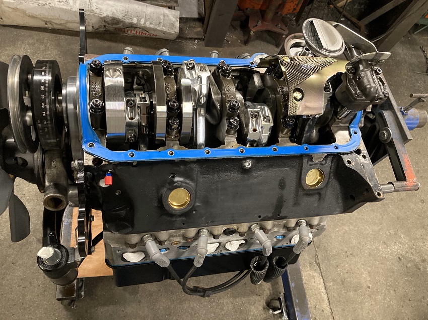
Low compression and BME aluminum rods help this stock block 355 live above 1000hp, the 41lb pendulum cut crankshaft has a bobweight of just 1492g. Aftermarket blocks worth having are around 200-225lbs, i've got this 010 block down to a little over 150lbs. I wanted to build it kind of like the old fuel engines with really low compression, so it could be sprayed really hard to achieve a higher average cyl pressure without having a really high peak pressure. In spite of the low compression ratio that only cranks about 100psi on the starter, Racepak data shows this engine gains NA no-load rpm at a rate of 11,515 rev/sec. You can see some weight removal from the block here...no side mounts and the stock fuel pump boss is gone...
To improve air circulation for better clutch cooling, the center hole in the block plate was enlarged...
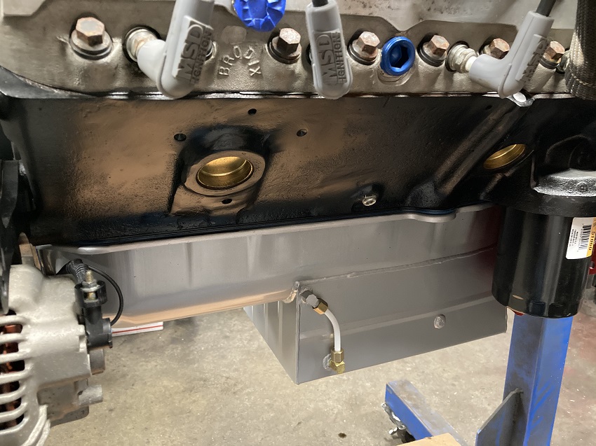
To eliminate potential air leaks that could reduce crankcase vacuum, the dipstick hole was plugged and a sight gauge was installed. This also allows you to see what the oil level is when the engine is running...
This 010 block's original fuel pump and motor mount bosses were removed to save some weight. In this shot you can see the entire fuel pump mounting boss has been removed, the aluminum plug you see plugs what's left of the original fuel pump pushrod hole. Below the aluminum plug is the fitting for the hose that goes to the Racepak's crankcase vacuum sensor...
Shop Mule Exhaust System...
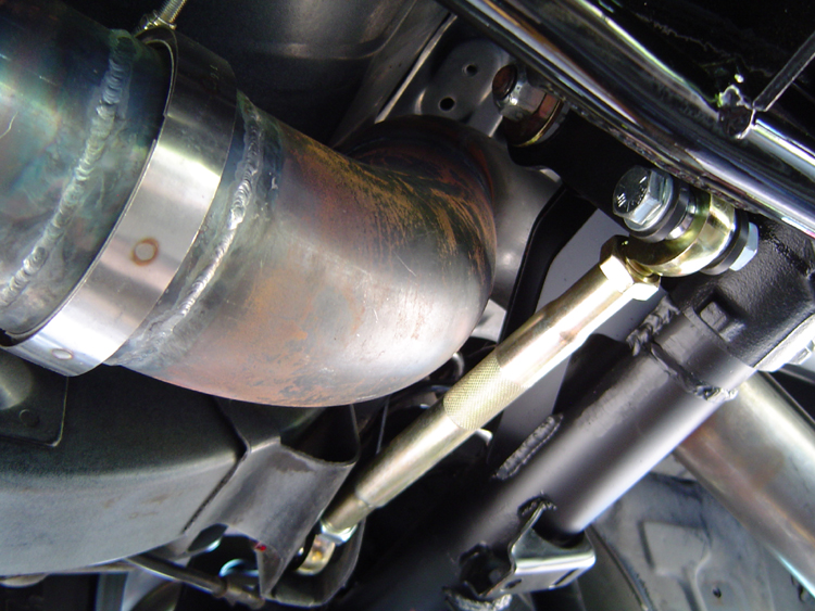
I routed the exhaust pipes out of the side of the extended collectors, and made some caps for the collectors themselves. Now when i uncork the pipes, it flows straight out the collector, not out the side thru a dump pipe. I made some short collector extensions that I add which feature a "tongue" that extends up into the collector to seal off the rest of the exhaust system, making the collectors more effecient. V-bands were used on the mid-pipes to make transmission/clutch maintenance easier.
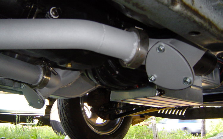
The entire exhaust system is hung with (4) stock RX-7 rubber hangers, 1 here before the axle, and 3 around the muffler. The sheetmetal bracket serves to isolate the rubber from the full heat of the pipe.
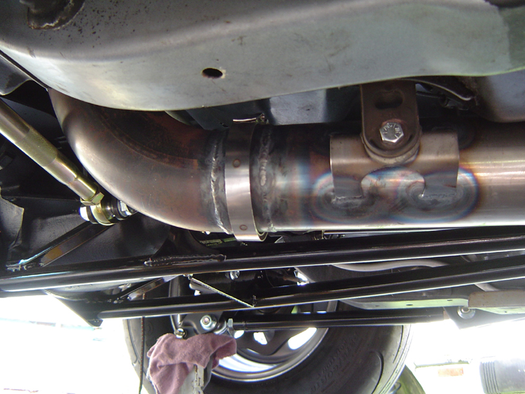
Here's a shot of the Torque Arm Suspension in the car. The nose of the TA is actually anchored up in the top of the tunnel with 2 huge rubber pucks. The shackle plates that connect the nose of the TA to the anchor assy do double duty as a driveline loop. The equal length exhaust merges into a single 3-1/2" pipe for the trip back to the muffler.
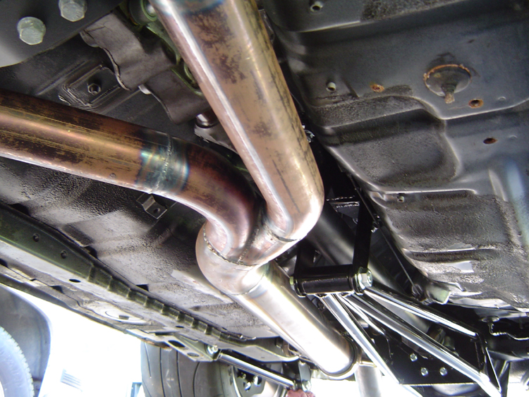
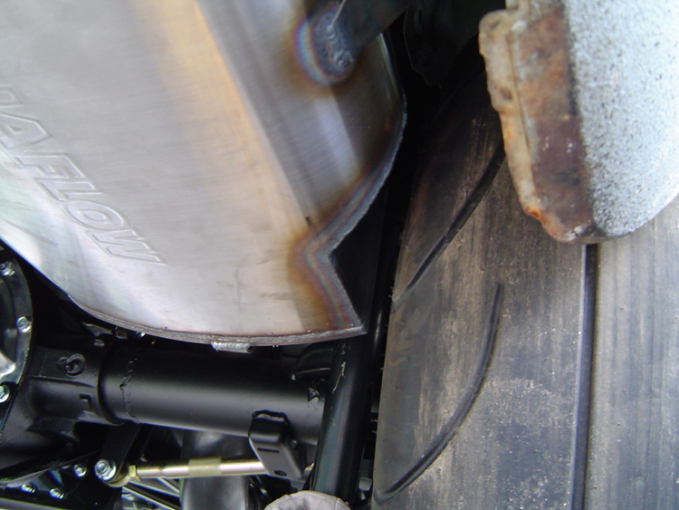
The 3-1/2" pipe fits up and over the axle with plenty of room...
The giant Magneflow muffler had to be notched to clear the RR tire...
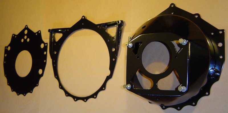
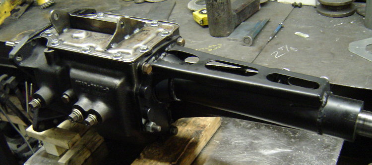
Update #1- Custom Steel Bellhousing Fabrication...
Basically, I made my own bellhousing to adapt a Ford Toploader 4spd transmission to my old school SB Chev V8. I can buy one for around $450, but it's a heavy 1/4" thick steel monster, and I prefer building my own lighter parts if i can. I'm not concerned about it not being "SFI certified", as it's just a fun street car and i have no desire to make it legal for the track.
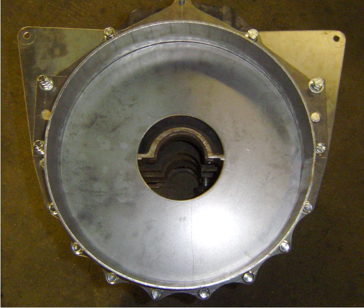
The mock-up began with an old 400 block and an empty transmission case. I used the alignment bar from my rearend narrowing jig to keep everything straight and true. I machined some steel pucks to fit in the block's main bearing bores and also the bearing bores in the transmission case. The pucks have an 1.501" hole in the center so that my alignment bar slides inside everything to keep the engine and transmission bores concentric. I made a ring to center the plate that the transmission will bolt to, and a tube spacer that will set the desired distance between the block and transmission face. I also made the rear plate that the transmission will bolt to, and laid out the the flange that will bolt to the block and serve as a pattern for the block plate that will fit behind the flywheel.
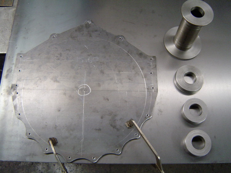
Here's the pattern I made out of 1/4" steel. All the hole locations were laid out, centerpunched, and drilled 3/16" so that the pattern could be transferred to the blank piece of 1/8" that it's laying on, which was used to make the block protection plate. The steel pucks on the right are the pilot rings and spacer that i mentioned in an earlier post that locate everything in the correct positions for mock-up. Later this pattern will get the bolt holes drilled and the large center hole will be cut out, turning the pattern into the flange for the front of the bell...
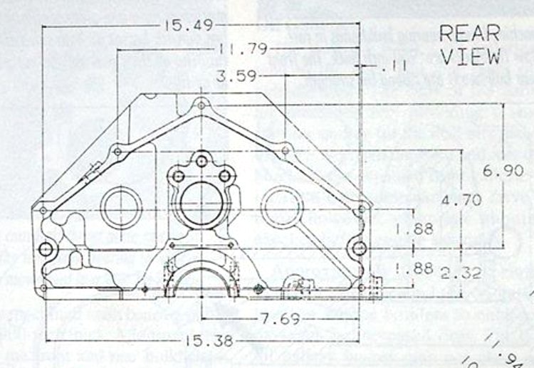
Here's the drawing I used to lay out the block bolt pattern...
This is the block plate after it was cut out and drilled. The large hole in the center is for the crank's flywheel flange to stick thru, and the 2 larger holes on the sides are for the locating dowels in the block...
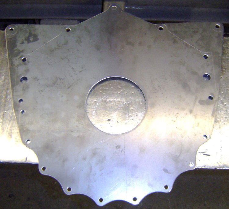
This is the pattern after i drilled it out and cut the center out. It is going to be the forward flange of the bellhousing that bolts to the block, the large hole in the center is necessary to clear the flywheel...
Here's the block plate on a block. The upper "wings" were added as mid-mounting points that will hang the back of the engine at the firewall...
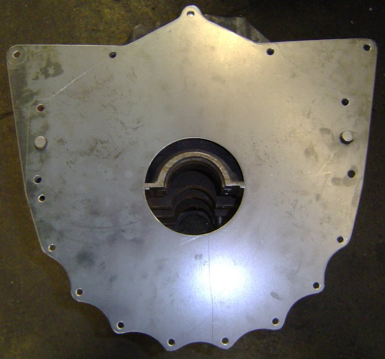
Here's the block plate and flange on a block. The block plate will be sandwiched between the block and bellhousing as shown. I'll soon be creating a hole and pocket for the starter.
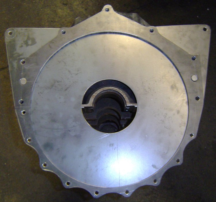
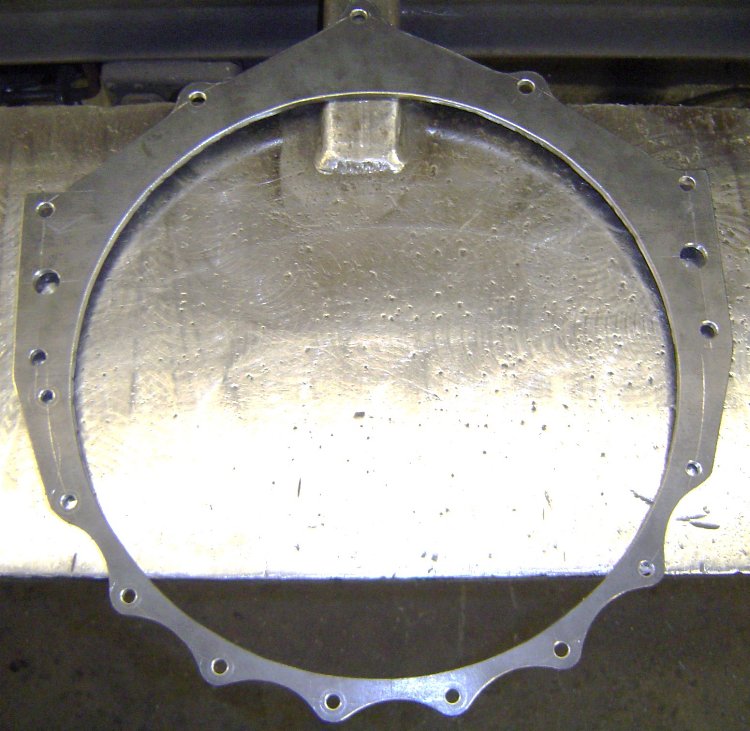
Here's a pic of the rolled ring welded to the bellflange. All the holes still fit perfectly...
The mid-mounts incorporated into the block plate allow me to easily remove the bellhousing/clutch/flywheel from the car without needing to support the engine. Greatly simplifies my clutch and transmission maintenance.
Here's the alignment bar in place in the block, as well as the spacer that sets the depth between the block and trans case...
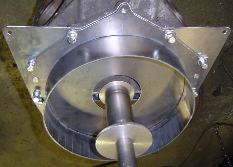
Here's the trans case in position located by the pilot rings...
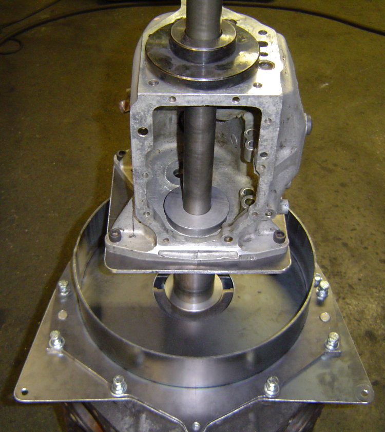
I had to take it out of the fixture to make sure i had created enough room to install a SoftLoc clutch, so i figured i'd snap a few pics of the progress.
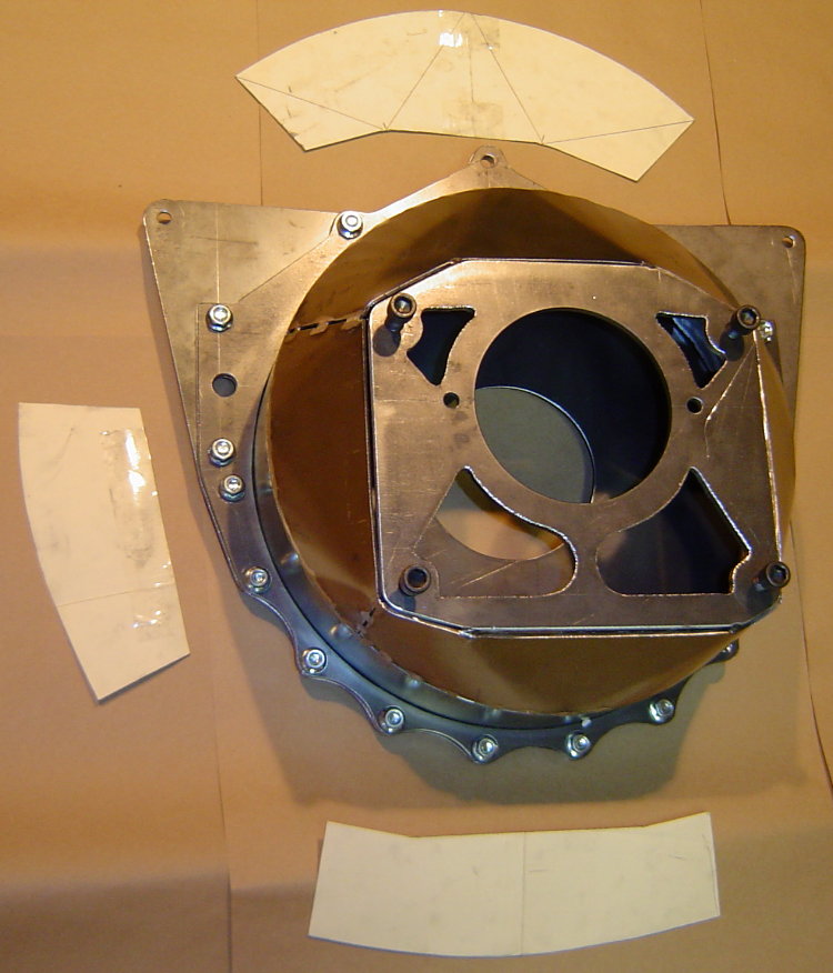
I started making patterns for closing in the bell by laying out the the top section on posterboard. I quickly realized it was much easier to just cut out slightly larger pieces of posterboard, hold them in place on the bell, and simply apply a little pressure by running my finger around the edges of the steel. This puts a small crease in the posterboard and transfers the exact shape needed, a much quicker way to create a pattern...
The transmission plate is still only tacked in 4 places. After all the rest of the welding is done, i'll put the bell back into the fixture, cut the tacks, and re-position the plate for the best alignment possible before welding it in place. I doubt there will be any need to machine the block or transmission mating surfaces.
Added a cutout for the mini-starter's drive...
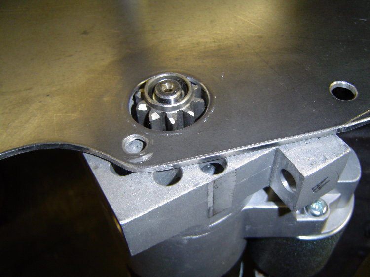
Added a starter pocket to the bell as well...
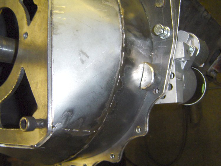
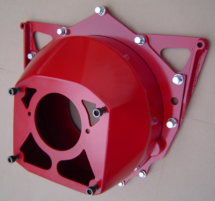
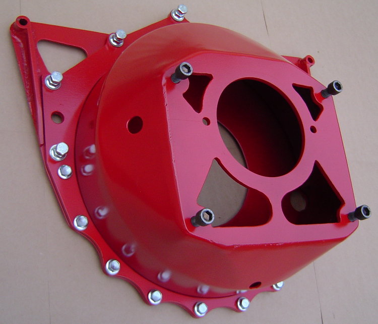
Here's the finished bellhousing...
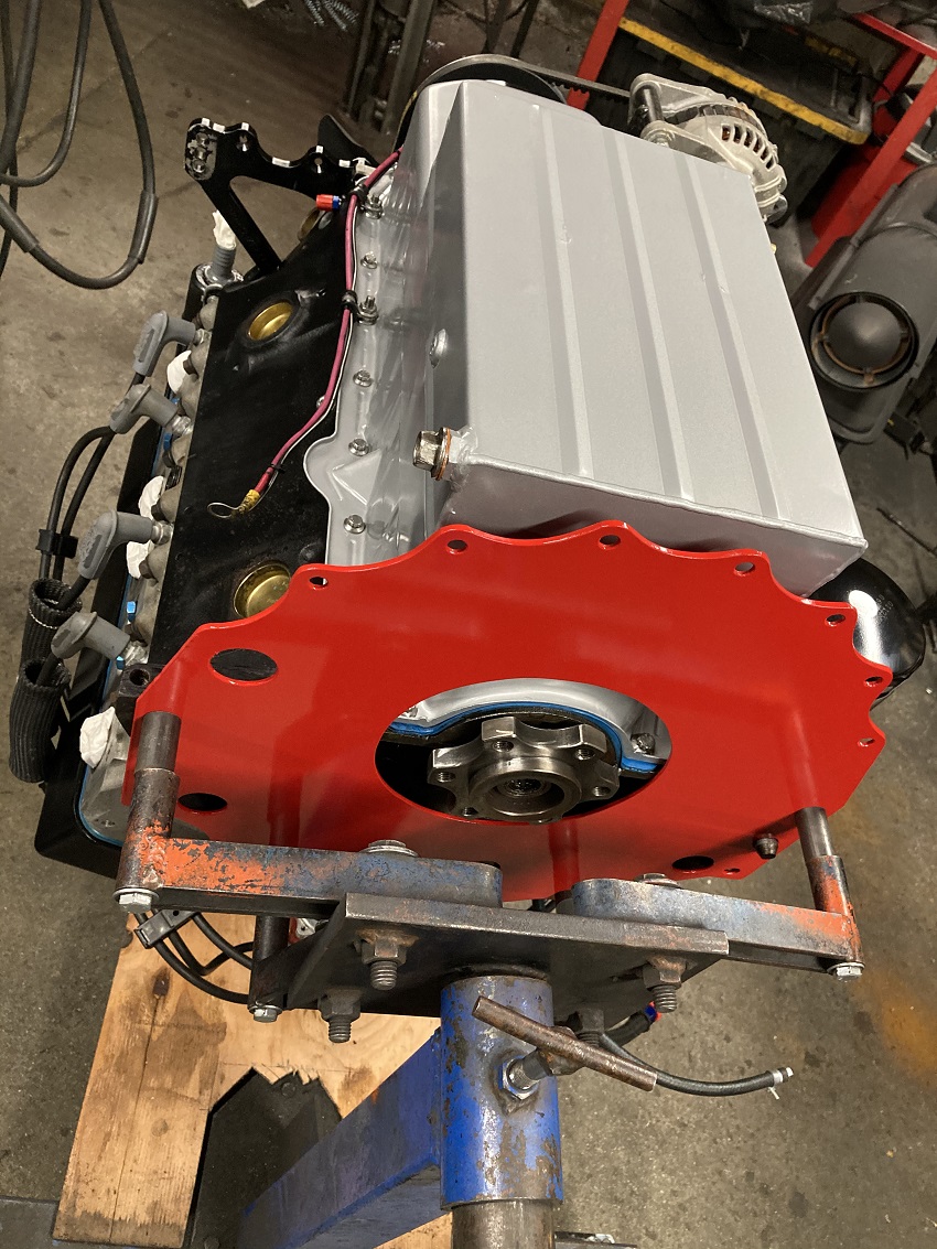
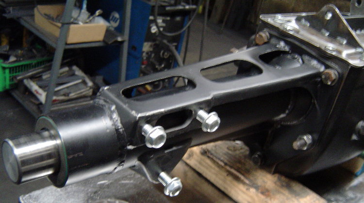
UPDATE-...I went to a 3pc style bellhousing...blockplate, midplate, bell/can. Now i can remove the engine from the car with the flywheel and clutch, and leave the bell and transmission mounted in the car. I can also remove the transmission/bell/clutch/flywheel from the car without supporting the rear of the engine. I also added a couple external "ears" to the block plate, which gives me some easy attachment points for lifting the engine...
Here's a pic of how/where the midplate's "ears" attach to the firewall...
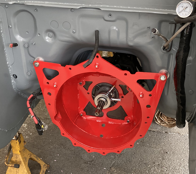
This shot from the inside shows one of the aluminum firewall reinforcements installed behind the firewall. They serve to spread the load over a wider area so that stress transferred from the midplate does not buckle the thin stock firewall's sheetmetal...
I'll take some pics of the engine lifting fixture i made for it. It plugs into the blockplate's added "ears" and into an "eye" that screws into a hole in the top of the waterpump. It fits over the complete engine with the aircleaner and distributor in place. Before i was always using some type of hokey chains trying to find a perfect balance point without damageing something. Now i have a dedicated fixture that plugs in and makes the job easy. Been thinking about attaching the radiator to the engine just to make choosing between a couple engines that much easier
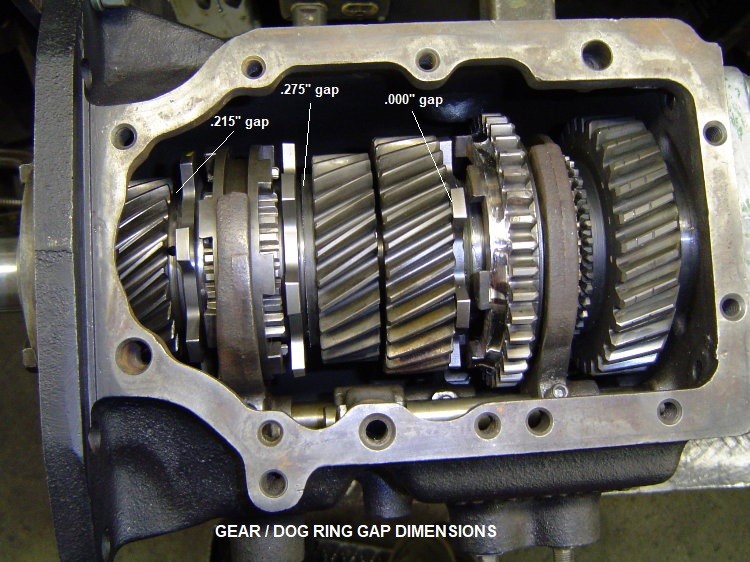
Update #2- Custom Faceplated Ford Toploader 4 Spd...
Who says you can't DIY faceplate 2nd gear in a Ford Toploader? Parts for 3rd & 4th gear conversions are available off the shelf from Liberty, but Proshift was the only upgrade available for 2nd. I took a set of 3rd/4th Liberty parts and modified them to fit...
Here's a pic of a trial fitting of 2nd inside the main case. The Toploader now has been faceplated in 2nd, 3rd, and 4th gears. Keeping the 1st gear synchro makes it easier to drive on the street, as you can slip it in and out of gear while idling at a stoplite. If you decide to faceplate your own Toploader (or have a local shop do it for you), this pic also shows the gap dimensions I use which tighten up the slider travel distance quite a bit over what you get when Liberty does it. My shifter knob travel is 1-1/2" from neutral in each gear, which translates to 3" overall arm movement when shifting...
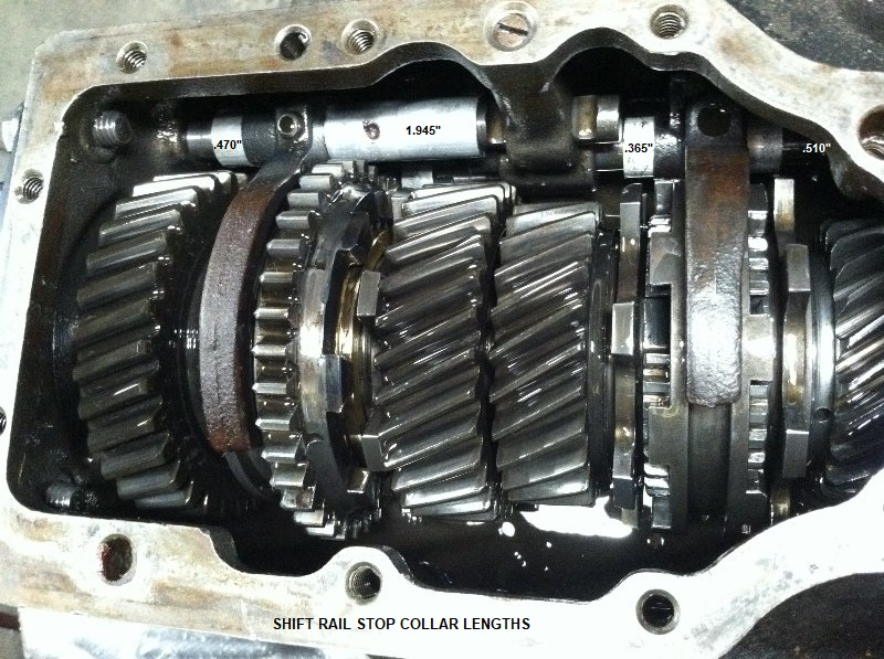
Here's the same transmission as above, except 5 years later. You can see some rounding of the edge of the 2nd gear dogs in this pic, we pulled the trans down to replace them. What you can also see is the aluminum shift rail stops we added on both sides of the shift forks. This greatly reduces the hammering effect of the rail's inertia on the forks, we have had no problems with bent or broken stock shift forks at all. This pic also shows the stop collar lengths that I use...
I originally bought 3 TKO dog rings and 2 TKO faceplate sliders from Liberty. Back in 2011 the dog rings were $65/ea, the sliders were $100/ea....
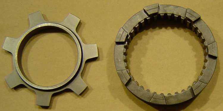
Machined the gears to accept the dog rings. Liberty slider for 3rd/4th gears was used as-is, no modifications. For the 1/2 slider, I slit one side off the extra 3/4 faceplate slider, then welded it onto the 2nd gear side of a stock Toploader 1/2 slider. Retained the original synchro setup on the 1st gear side. Ended up with synchro 1st, faceplated 2/3/4. Here's a pic of the parted off section of Liberty faceplate slider sitting on the stock slider...
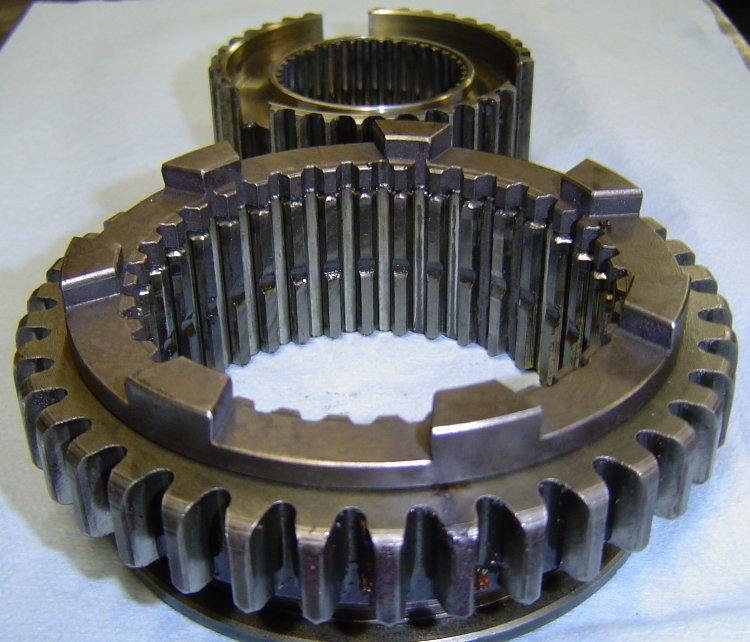
Here's a pic of the slider after welding on the faceplate ring. Note that reverse gear teeth on the stock slider were narrowed to make room for the weld, the inner teeth of the faceplate ring were also removed...
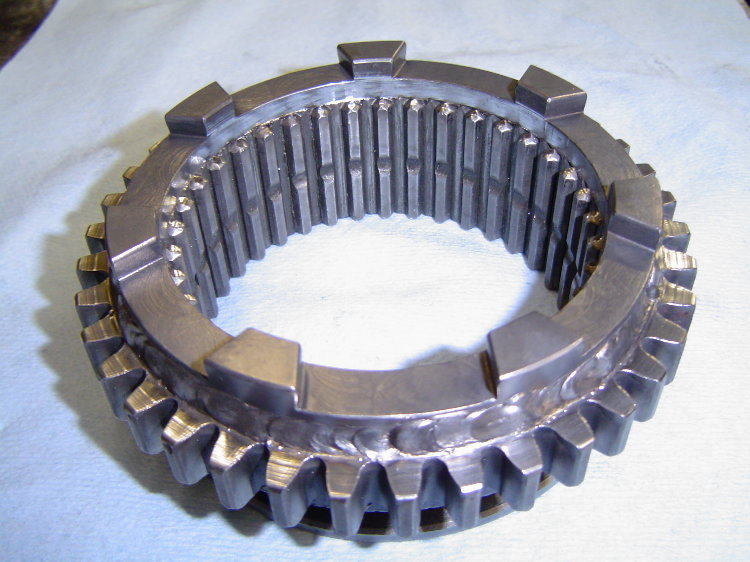
All this was skip welded using common .035" MIG wire, air blast cooling between welds to protect the heat treat of the engagement lugs.
This transmission has been in the car for around 10 years now, no broken gears, shafts, or shift forks to date. I have replaced faceplate parts a few times due to wear/tear, also replaced a few twisted small input shafts and Spicer 28spl slip yokes. Still has the same 28spl SROD output shaft that was installed in 2011, it's splines are still straight. Went to a 28spl billet Sonax slip yoke a few years ago, it's splines are still straight as well. Car is currently using a Hitmaster clutch hit controller. It's configured to soften the hit for around 1.0 sec during launch, but also comes on for 0.5 sec after the shifts. Without the unit active for WOT shifts, the Toploader's small input shaft splines twist.
To lighten up the cast-iron Toploader, I made a .065" sheet steel tailhousing for it, eliminating the pad for the trans mount and moving the shifter mount pad to the passenger side of the tailhousing (allows fabrication of a smaller/lighter shifter mounting bracket). In this pic you can also see the external "rail style" shift linkage guides that are welded to the Toploader's original sheetmetal top cover. This style linkage allows mounting the shifter above the output shaft, overall it's similar to the Saginaw shift linkage shown two pictures below...
Fabricating our own tailhousing from steel saves weight over aluminum due to use of thinner materials, also allows for a more efficient shifter bracket location. There is no trans mount on this car, but there is a crossmember under the tailhousing to stiffen the tunnel. The complete Toploader with it's cast iron main case, sheetmetal tailhousing, oil, and slip yoke weighs in at 91.4lbs. A complete T5 with it's aluminum case and tailhousing weighs about 80lbs with oil.
I don't have a picture of the shifter installed on the Toploader, but it is basically just like the one pictured below that i made for a Saginaw 4spd back around 2008. Looking at this picture you can see why I moved the shifter mount to the right side of the fabricated Toploader tailhousing...
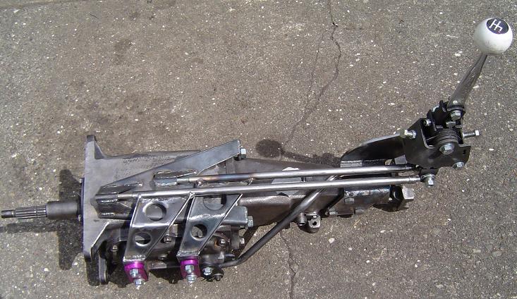
This puts the shifter up in the perfect spot for the RX-7's console opening. The short stick, combined with the tightening up of the Toploader's faceplate spacing, reduces the shifter's total "throw" to only 2".
Update #3- Experimental Clutch Slip Controller back in 2010...
In the beginning i was just looking for a way to reduce transmission breakage, but I soon found it had much more potential than just saving parts. Basically it was a small hydraulic screen door closer cylinder that connected to the clutch pedal with a simple bracket. This was the original prototype version of the ClutchTamer that I originally called the "Hillbilly Clutch Slipper"...
Turning the black knob adjusted the clutch pedal's release rate, adjusting the inner dial on the threaded rod moved the point in pedal travel that the cylinder becomes active. It was an effective, no hassle way to completely eliminate any sign of a bog, and almost made it too easy to hook radials with a stick.
The above slip controller was used on a 2800lb Ram diaphram pressure plate, and a Ram sintered iron disc. It was a more street-friendly alternative to the high-maintenance Mcleod SoftLoc clutch, which uses a Long style PP that needs frequent adjustments of the spring pressure and occasional pressure plate shimming. My version can easily be adjusted from the driver's seat, and does not effect normal street driving.
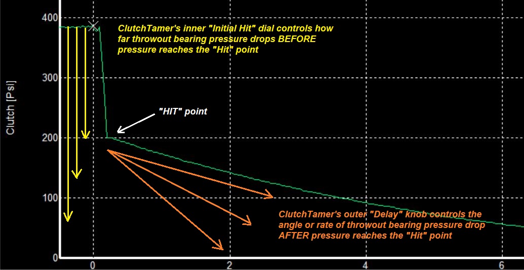
Here's a graph showing typical shape of the throwout bearing PSI curve with the ClutchTamer controlling clutch engagement...
The Clutch Slipper project has evolved a bit, and has become a business all it's own. Check it out here at ClutchTamer.com
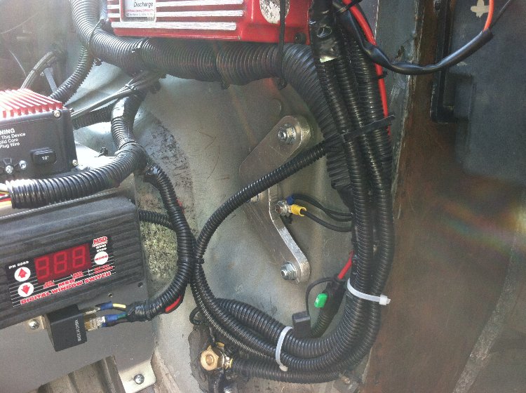
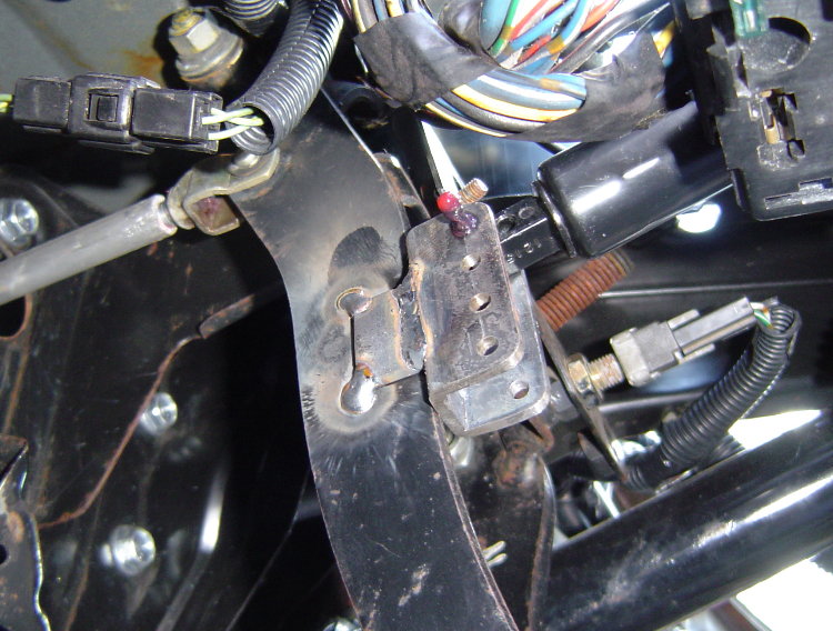
Update #4A- Developing the HitMaster 2-stage Clutch Slip Controller back in 2018...
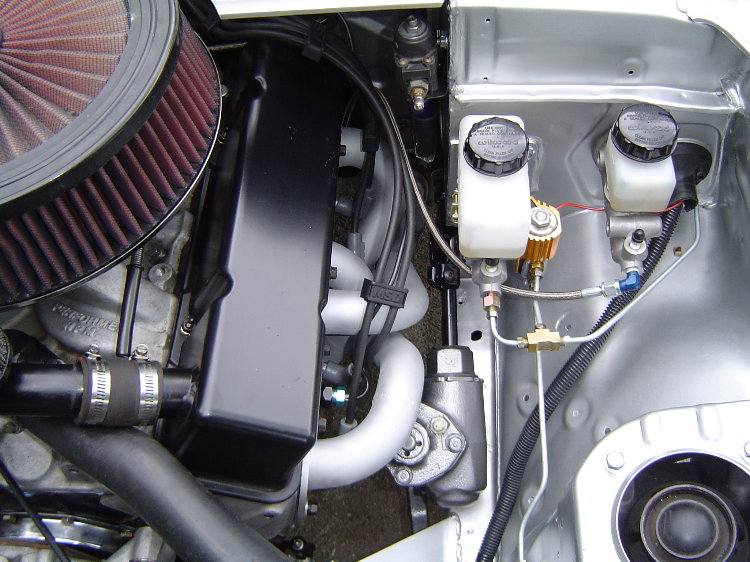
My Shop Mule was the original testbed for developing the HitMaster 2-stage clutch hit control system. Pic on the left shows the system's 2nd stage transition valve installed on the Shop Mule's clutch master cylinder...
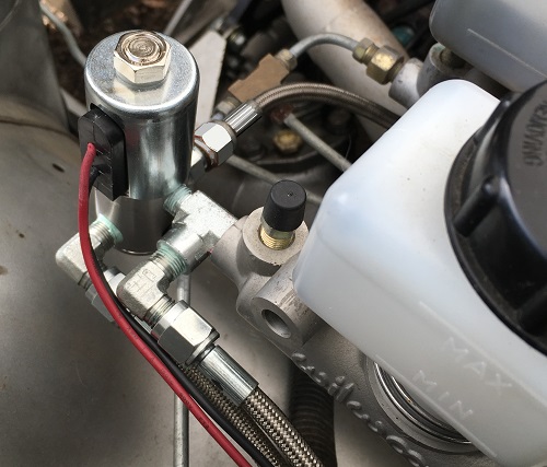 .....
.....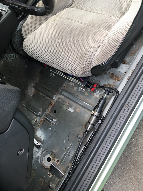
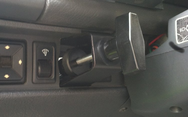
Pic on the right shows the HitMaster valve and dual timer install inside the Shop Mule. The timers are mounted to the aluminum panel that's almost hidden under the front edge of the seat. Left timer sets the clutch transition point after launch, the right timer sets the clutch transition point after the shifts. Here's a graph showing typical shape of the throwout bearing PSI curve with the Hitmaster System controlling clutch engagement...

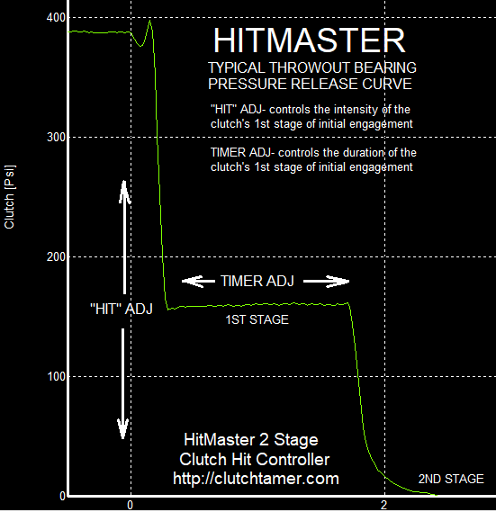
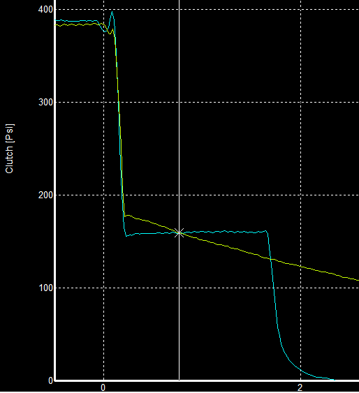
Here's a graph showing a comparison of the ClutchTamer and Hitmaster release curves. Let's say the ideal hit for a given chassis would be about 160psi, which happens to be about where the two traces intersect. The ClutchTamer's degrading curve needs to hit above 160psi in order to keep from dropping below 160psi too quickly. The stepped shape of the Hitmaster curve allows psi to drop instantly to the sweet spot, so it hits a little harder without danger of dropping past the sweet spot too quickly...
2023 UPDATE: Times are changing guys! Buy some good radials, add a good clutch hit controller, enjoy consistent dead hook launches without bog or broken parts. No need to swap between slicks for the track and radials for the street. No need to buy a fancy Long style adjustable clutch or swap back and forth between street and track clutch tunes. Good chance you can shave a half second or more off your ET just by softening the hit of an off the shelf diaphragm clutch. Probably the most cost-effective thing you can add to a stick shift car for the drag strip. They works on bias slicks too, will even add adjustability and ease of tuning to your expensive adjustable Long style clutch!
I've been on the web for years preaching the benefits of clutch hit controllers. I'm not sure if some guys think they are snake oil or some sort of a band-aid gimmick, but these things are real and they are winning big races. They've won A/S at NHRA's US Nationals on radials, brought home the $10k winner's check in the 200+mph stick shift class at the 2022 World Cup Finals, also just brought home the $10k stick shift class check at the recent Texas2k23. Most every screaming 7200+ dead hook launch of an NMRA Coyote Stock champ for the last 5 years or so has been softening the hit of a diaphragm clutch with a clutch hit controller. Been used in SEGA as well as the salt flats, BC Super Shifters and Rocky Mountain Stick Shifters, Drag Week, Turbo Dune Buggys, even Subaru has used them on standing start rally cars!
In the words of NHRA's national event track prep guy, "all clutch cars should have a tamer� because they don�t rip the shit out of the track!"
To find out more about my ClutchTamer and Hitmaster 2-stage clutch hit control systems and how they work CLICK HERE
Update #5- Crankcase EVAC System...
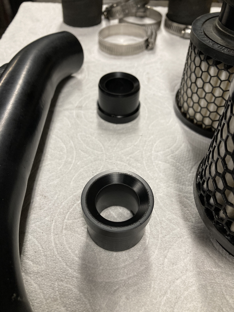
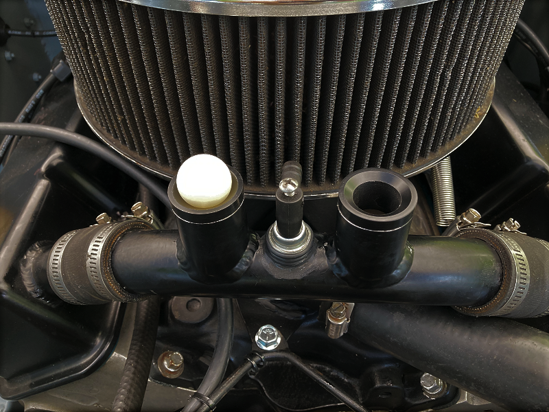
Here's some pics of the evac system currently on the Shop Mule. The pcv valve in the center of the pic is the engine's only crankcase vacuum source...
My current system features a set of check valves inside the breathers, which makes it possible for the pcv valve to draw a vacuum inside the engine. The push-in check valve seats were machined from Delrin, the check balls themselves are 1" dia nylon bearing balls...
I've been running a pcv/sealed crankcase setup since 2012 with a couple different engines, with crank seals are reversed. Rear seal is a fluoroelastomer 2912 Felpro, which seems to last pretty good reversed against this much vacuum. Front seal is viton SCE 21102, it had to be replaced last winter. I think next front seal will be one designed for a reverse rotation boat engine, my thinking is that the small directional ribs going in the wrong direction will help lube the seal lip. No signs of wrist pin oiling issues @ 15-16"Hg.
Here's a RacePak graph from 3 years ago showing crankcase vacuum during a 6.25sec long WOT 3rd gear pull...
...Red line- engine rpm
...Blue line- WOT switch
...Yellow line- crankcase vacuum
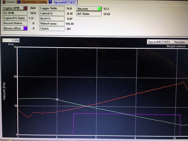
The pull started out with 12.6"Hg @ 2600rpm. When the pull ended at 6250rpm, the crankcase still had 3.9"Hg of vacuum left. I should add that the engine is well sealed, no dipstick (oil level sight tube).
This car has no overdrive, it's 3133rpm @ 70mph. Took it on a long drive across the pass a few weeks ago, including a 8610rpm blast inside a tunnel, and still got 20.98 mpg. Low tension rings are the biggest reason it gets great fuel mileage while spinning that fast without overdrive. A pcv valve, combined with a sealed crankcase, is the key to making those low tension rings work on the highway without excessive oil consumption. If the crankcase ever goes positive pressure, the check valves open up to relieve the pressure thru the breathers.
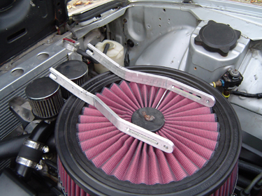
Here's something we came up with to help get the ShopMule down to 2325lbs while keeping it street legal...a couple of simple headlite support struts. The purpose of these struts is to hold the headlites in the upright position for night time driving, after the original actuator motors and linkage have been removed. Easily stashed in the glovebox, these lightweight struts install in less than a minute when needed, no tools required. We made them out of 1/4 x 1" aluminum...
 ..
..
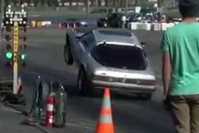
20mpg, 87 octane gas (even when spraying), driven everywhere, usually the quickest car that drove thru the gate. Much more fun than a race-only car. Just a fun street toy that I use to develop my clutch control products. Doesn't have any chassis reinforcements or even a roll bar, only a modified sway bay from a Crown Vic added to the rear instead of an ARB. Usually gets out on random Friday nites during the summer...
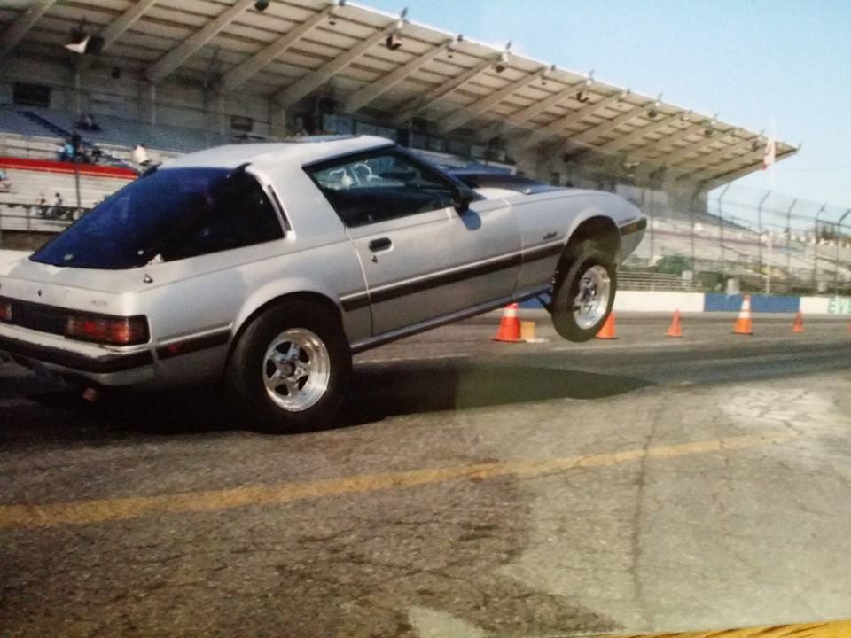
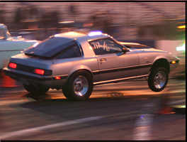
Here's some old pics of it running the front straightaway of a paved 5/8mi oval back in 2011, putting in work gathering data for my clutch control products. I was very lucky that this car still had the original rebuildable front struts when I got it. Note that the typical fix for a worn RX-7 front strut is to install a cartridge, which shortens the available travel distance. I took the originals apart and changed the shim stack to get the valving I wanted. As you can see below, those original rebuildable front struts have plenty of travel!
 .
. .
.
 .
. .
.

Click on the logo below to check out my ClutchTamer and Hitmaster clutch control products...
.