
The connector descriptions listed here are the '93-'95 style that are typically square or rectangular in shape.
Emissions Harness... this harness is located on the passenger side of the engine compartment. It contains wires between the rotary
engine's ECU to the rotary's injectors and ECU sensors. This harness will be removed when performing an engine swap.
Engine Harness... this harness is located on the driver's side of the engine compartment. It contains wires
to the rotary engine's battery cables, ignition system, starter, alternator, oil pressure sender, transmission switches, dash gauges, and various warning sensors. This harness is no longer needed, but it contains
some connectors which should be salvaged for later use.
Front Harness... this harness is the main harness for the front of the RX-7. It's basic job is to connect all the other sub harnesses
in the front to the rest of the car. It comes thru the firewall on the extreme driver's side of the firewall, and runs forward to the
radiator support to the relay rack (under the plastic cover in front of the radiator), and across to the horns, the coolant level sensor
(in the top of the RX-7 radiator), headlites, front parking lites, etc.
Connector X-11...this is a small square "grey" 4 pin connector (right next to "grey" X-12)between the "front" and "engine" harnesses, located just ahead of the RX-7's driver's side shock tower.
...black w/ red stripe...connect this wire to your Chevy engine's starter solenoid "S" terminal.
Connector X-12...this is a large rectangular "grey" 4 row 12 pin connector (right next to "grey" X-11)between the "front" and "engine" harness, located just ahead of the driver's side shock tower.
...grey w/ red stripe...this wire goes to the rotary engine's oil pressure sending unit that is installed in your LT1.
...brown w/ white stripe...this wire went to the RX-7's coolant level sending unit located in the RX-7's top radiator tank. Grounding this wire will silence the RX-7's coolant level warning "beep".
Connector X-14...this is a rectangular "white" 2 row 16 wire connector (1 row of 6, 1 row of 8, 2 wires missing) between the "emissions" and "dash" harness, located under the dash on the passenger footwell area. It's the white connector up behind the RX-7's blower motor near where the emissions harness passes thru the firewall.
...yellow w/ red stripe...this wire went to the signal side of the RX-7's VSS sending unit, which was located in the driver's side of the RX-7 transmission's tailhousing. If you are salvaging the emission's harness side of this X-14 connector, this wire changes to green.
...yellow w/ white stripe...this wire went to the ground side of the RX-7's VSS sending unit, which was located in the driver's side of the RX-7 transmission's tailhousing. If you are salvaging the emission's harness side of this X-14 connector, this wire changes to orange.
...gray...this wire went to the rotary engine's water temp sending unit that is installed in your LT1.
...black wire w/ yellow stripe... comes from 15a fuse in underdash fusebox. This is the power source for the back-up lites.
...red wire... goes directly to the back-up lites.
...black wire...this large gauge wire needs to be grounded to BOTH the chassis AND to the engine.
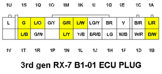
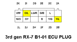
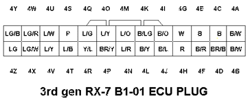
Connector B1-01 plugs...these (4) connectors are located behind the right side kick panel in the passenger compartment. They were formerly arranged in a row along the front side of the RX-7's ECU, which is now removed. The wire locations and color code are shown in the illustrations below. The yellow highlighted wire locations are the ones that we will be either modifing or connecting to the LT1's PCM. The IDs of the highlited wire locations are listed below the illustrations. The non-highlited wires are no longer needed, and we will not be connecting them to anything.


This guide lists the connections required to the stock Camaro/Firebird PCM/engine harness to allow engine operation. The guide assumes that all sensors/relays/solenoids etc that were formerly connected to the harness are still properly connected and in good working order. The connectors listed formerly connected to other harnesses in the Camaro.
LT-1 Harness Connector C-210...
Formerly located passenger side footwell in Camaro
Black - 4 terminals - 1 row of 4
C....orange....connect to 10a fused 12v constant power.
LT-1 Harness Connector C-220...
Formerly located passenger side footwell area in Camaro
Natural - 10 terminals - 2 rows of 5
J....dark green/white stripe wire. The LT-1 PCM uses this dark green/white wire to turn the fuel pump on.
LT-1 Harness Connector C-230...
Formerly located passenger side footwell area in Camaro
Blue - 10 terminals - 2 rows of 5
B....brown/white....connect to ground side of a lite labled “service engine soon” (required to be smog legal). Other side of
.......“SES” lite should be connected to 12v “+”.
C....white/black....connect to diagnostic plug (diagnostic request signal).
D....white....tach signal from LT1 PCM. Connect to RX-7 tach thru Dakota Digital SGI-5tach.
G....pink....connect to 12+ power source hot in "start" and "run".
.......LT-1 harness’s ignition coil “+”).
H....lt blue/black....AUTO- connect to brake switch (switch open when brake is depressed)
.......brown.............MAN- connect to RX-7 connector X-04 black w/ yellow stripe wire (power side of reverse switch).
J....orange/black....AUTO- connect to (park / neutral feed from trans shifter position switch)
.......green..............MAN- connect to RX-7 switched side of reverse switch (to back-up lites)
LT-1 PCM connector A...
Red
A-7...dark green/white....This connection is required or LT-1 PCM sets a code. Connect/tap into RX-7's white w/ red stripe wire (fuel pump “+”).
Granny’s VATS eliminator module...
blue (or green)....connect to LT-1 PCM’s A-25 terminal (5v 50hz signal out enables LT-1’s injector power)
red....connect to LT-1 PCM’s B-29 terminal (B-29 is a 5v power source)
black....connect to LT-1 PCM’s A-2 terminal (ground)
ECU / PCM Transplant...the LT1's PCM connectors...
There are (4) color coded 22 pin rectangular connectors plugged into the LT1's PCM. Below are the layout illustrations and wire color codes for each.
Connector A is grey.
Connector B is red
Connector C is green
Connector D is brown
2....Considerations & Requirements....
4....Engine / Transmission Installation....
5....Exhaust / Throttle Cable / Accessory Drive / Pulleys....
6....Cooling / Fuel Systems....
7....RX-7 Wiring Harness Connector ID and Circuit Locations....
8....Electrical System Modifications By Circuit....
9....Start-up / Troubleshooting....