Re-connecting The Battery To The RX-7's Harness...
The battery, the large top terminal on the Chevy starter solenoid, the RX-7's power distribution block, and the large terminal on the back of the alternator need to all be connected to each other with large wire of at least 6ga size. When your battery is re-located to the rear of the car, this large gauge wire should extend all the way to the battery "+" terminal.
Be sure to connect the chassis and block together with a large ground cable of at least "00" guage, as the engine/trans are somewhat isolated by the rubber engine/trans mounts. Without a large seperate ground wire, smaller ground wires will become overloaded and possibly melt during periods of hi current draw, such as when the starter is engaged.
Starter Wiring...The wiring for the Chevy starter is almost identical to that of the RX-7.
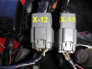
The problem is that the RX-7 starter solenoid's "start" wire was part of the engine harness, which was removed with the rotary engine. You can access this black w/ white stripe wire at the small 4 pin grey X-11 connector (listed in the harness ID section) located next to X-12 in front of the driver's side strut tower.
...Manual trans T-5 and T-56 applications...Route a wire from X-11's black w/ red stripe wire that extends to the Chevy starter solenoid's "S" terminal.
...T-350/T-400/2004R/700R4/4L60E automatic trans applications...Route a wire from connector X-11's black w/ red stripe wire that extends thru the neutral safety switch, then to the Chevy starter solenoid's "S" terminal. Be sure that the neutral safety switch interrupts this wire in all shifter positions except neutral and park. If it does not, adjust the switch until it does.
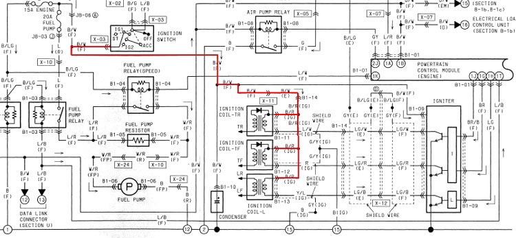
Ignition Wiring...Power for your engine's ignition system should come from the connector that went to the rotary engine's "Trailing Coil w/ Igniter", that was located on the inner fender panel behind the driver's side strut tower. Power for this black w/ yellow stripe wire come from a 40amp fusible link, and is turned "on" by the "Main Relay" when the ignition switch is in either the "start" or "run" positions.
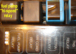
Eliminating The RX-7 Fuel Pump's "hi-speed" Relay & Resistor...Located in the The 3rd gen RX-7's fuel pump was controlled by it's ECU, which grounded the coil in the circuit opening relay (blue w/ black stripe wire) to turn the fuel pump on. When the rotary seen boost conditions, it's ECU upped the voltage to the fuel pump by grounding the coil in the fuel pump relay (blue w/ white stripe wire), causing the relay to bypass the fuel pump resistor, increasing fuel pump output. Many simply wire around the resistor or eliminate the fuel pump relay and resistor altogether to acheive maximum fuel pump output at all times. We prefer to eliminate the RX-7 resistor and fuel pump relay altogether by unplugging the relay's B1-04 connector and connecting the fuel pump's white w/ red stripe wire directly to the circuit opening relay's blue w/ red stripe wire (both wires are in the B1-04 connector).
Modification to the wiring for the RX-7's Circuit Opening Relay (fuel pump relay)...Located inside the relay/fuse box located on the RX-7's right side shock tower. The following modifications are required to enable the RX-7's ignition switch to directly control the fuel pump. Basically we are changing from a ground enabled control to a power enabled system. Locate the blue w/ black stripe wire in the RX-7's B1-01 connector. Simply grounding this wire will enable the RX-7 fuel pump at all times when the RX-7's ignition switch is in either the "start" or "run" positions. To maintain a measure of safety, this wire needs to be routed to ground thru both an inerta switch and an oil pressure switch, wired in parallel. The inertia switch will allow the fuel pump to run as soon as the key is turned on for quick starts. The oil pressure switch serves to over-ride the inertia switch during violent drag launches. This way the key has direct control over the fuel pump UNTIL the engine dies AND the car is involved in a crash.
RX-7 Dash Harness Ground...this connection is important for functioning gauges and dash lites. The connection is different depending on what transmission your RX-7 originally came with.
...manual trans from factory...ground large black w/ blue stripe wire in salvaged emissions harness side of RX-7 connector X-14. If you are working with the front harness half of this X-14, this wire changes to black.
...automatic trans from factory...ground the black w/ blue stripe wire in RX-7 connector X-05, a blue 22 pin connector located behind the firewall in the passenger footwell area, below the RX-7's X-14 connector.
Temp Sender Location & Installation...The RX-7's rotary engine's temperature sending unit for the dash gauge is a very small single terminal device located below the rotary engine's oil filter. It can be removed from the rotary and installed in your V-8' cylinder head (between the #1 and #3 exhaust ports) using a special reducing bushing. After installation, the sending unit should be connected to the yellow w/ white stripe wire in the salvaged emissions harness half connector X-14. If you are tracing the dash harness half of X-14, this wire changes to grey. The original connector for the sending unit can be salvaged from the discarded emissions harness and re-used here for a factory quality connection.
Oil Pressure Sending Unit Wiring... The rotary engine's oil pressure sending unit for the dash gauge is located large round single terminal device located below the rotary engine's oil filter. It can be removed from the rotary and installed in the rear of your V-8's engine block (located just to the driver's side of the distributor in the top/rear of the block) using a 1/8" pipe thread 45 degree elebow fitting (male threads for the block, female threads for the sender). A single wrap of the threads with teflon tape should ensure leak free operation. After installation, the sending unit should be connected to the grey w/ red stripe wire in RX-7 connector X-12. The original connector for the sending unit can be salvaged from the discarded emissions harness and re-used here for a factory quality connection.
Alternator Wiring (using RX-7 alternator)...Simply extend your RX-7's existing alternator wiring to your alternator's new location.
Speedometer Signal Wiring...The RX-7's speedometer originally got it's signal from a generator mounted on the driver's side of the RX-7 transmission's tailhousing. The easiest way to correct this is to use a "digital ratio adapter", such as the Dakota Digital SGI-5B, which is wired as follows...
...SGI-5B PWR...connect to RX-7 B1-01 ECU plug terminal 1B, a 12v switched power source that comes thru the RX-7's main "EGI" relay.
...SGI-5B GND...connect to salvaged emissions harness half of RX-7 X-14 connector's orange wire (wire color changes to yellow w/ white stripe on the dash harness side of X-14). This wire should also be connected to a good chassis ground such as one of the former RX-7 ECU mounting studs.
...SGI-5B SIG IN...connect to VSS signal generator "+" lead
...SGI-5B OUT...connect to salvaged emissions harness half of RX-7 X-14 connector's green wire (manual cars) or green w/ black stripe (automatic cars) (wire color changes to yellow w/ white stripe on the dash harness side of X-14). Use output 3, and set the dip switches as follows...
......dip #1- on
......dip #2- on
......dip #3- off
......dip #4- on
Tachometer Signal Wiring...The RX-7's tachometer originally got it's signal from the rotary engine's ECU. Simply connecting the V-8's tach signal to drive the RX-7 tach will result in a reading that is twice the actual V8 engine speed. The easiest way to correct this is to use a "digital tach adapter", such as the Dakota Digital SGI-8, which is wired as follows...
...SGI-8 PWR...connect to RX-7 B1-01 ECU plug terminal 1B, a 12v switched power source that comes thru the RX-7's main "EGI" relay.
...SGI-8 GND...connect to chassis ground at the same place as the RX-7 X-14 connector's large black wire. This wire should also be connected to a good chassis ground such as one of the former RX-7 ECU mounting studs.
...SGI-8 SIG IN...connect to your V-8 ignition system's "tach" output.
...SGI-8 OUT 1...connect to RX-7 B1-01 ECU plug terminal 2B, a yellow w/ blue stripe wire which was formerly the signal input point for the RX-7 tach.
Back-up Lite Switch...to operate the RX-7's back-up lites, Mazda used a transmission mounted SPST switch to complete the circuit.
When the RX-7's emission harness is removed with the rotary engine, part of this circuit is removed as well.
To restore this circuit, a 2 wire harness extension to the new reverse switch will need to be added from connector X-14, a rectangular 2 row 14 wire connector (1 row of 6, 1 row of 8, 2 wires missing) between the "emissions" and "dash" harness, located under the dash in the passenger footwell area. 2 of the wires in this connector are for the back-up lite switch. Wire colors for this circuit change as they pass thru X-14. If you are tapping into X-14 by salvaging the discarded male emissions harness side of X-14, these wire colors are...
...green w/ yellow stripe (manual trans) or black wire w/ yellow stripe (auto trans)...from 15a fuse in underdash fusebox.
...yellow w/ red stripe (manual trans) or brown w/ black stripe (auto trans)... goes to back-up lites.
Connecting these two wires together w/ a jumper wire will turn on the RX-7's back-up lites when the ignition switch is in the "ignition" and "start" positions.
Routing and connecting these two wires to your new transmission's back-up lite switch will enable the RX-7 back-up lites when "reverse" position of the shifter is selected.
Low Coolant Level Warning Buzzer and Lite...the warning buzzer was an absolute necessity for the rotary engine, but is generally not worth the trouble when installing a V8. To dis-able the annoying coolant alarm buzzer, simply ground the brown w/ white stripe wire in connector X-12.
AC System- Relay, Compressor & Pressure Switch...Only 2 circuits need modification for your AC system to function properly.
...AC relay (G-02)... in the #2 position in the relay box located in the nose of the car just to the passenger side of the hood latch. It has a square connector with 4 wires attached. It's terminals need to be re-connected as follows...
......blue w/ black stripe wire...connect this wire to one leg of the RX-7's pressure switch located near the RX-7's reciever/drier. The other leg of the pressure switch connects to "12v +" thru the "AC ON" switch.
......yellow w/ black stripe wire...connect this wire to ground.
......black w/ red stripe wire...connect this wire to the "+" side of your compressor's magnetic clutch. Connect the other leg of the magnetic clutch coil goes to ground.
......yellow wire...connect this wire to a "12v ign on" power source.
...AC pressure switch...a 2 terminal switch located next to the RX-7's reciever/drier. The switch's harness connector can be clipped from the front harness and re-used. The 2 legs of this switch/connector can re-wired as follows...
......violet wire...connect to "12v +" thru the "AC ON" switch.
......grey w/ red stripe wire...connect to the AC Relay's blue w/ black stripe terminal.
This guide will help you locate and identify the RX-7 harness connectors for required connections and modifications...
 ...X-1 Main Fuse Block...is the power distribution and fusible link block that was formerly located on the positive terminal of the RX-7's stock battery.
...X-02 Relay and Fuse Block...is the fuse and relay box that is located on the driver's side shock tower that contains the fuel pump relay, EGI main relay, and fuses for the AC, ABS, defroster, and cooling fans.
...X-05 Connector...is a blue connector located in the passenger footwell area. The actual connector size is different depending on if the RX-7 was originally equipped with a manual trans or an automatic trans.
............manual trans...12 pin connector
............automatic trans...22 pin connector
...X-11 Connector (location pictured on right)...is a grey 4 pin connector located in front of the driver's side shock tower.
...X-12 Connector (location pictured on right)...is a grey 12 pin connector located in front of the driver's side shock tower.
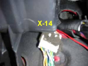 ...X-14 Connector (location pictured on right)...is a white 14 pin (manual trans) or 18 pin (auto trans) connector located under the dash behind the blower motor, behind the glove box, near where the harness passes thru the RX-7 firewall on the passenger side. The female side of X-14 is attached to the dash harness. The male side is is attached to the emissions harness, and is removed with the rotary engine ECU. We suggest that you retain the male emissions half of X-14, along with a section of connected wires, as an easy way to access X-14 without having to work upside down under the dash. Be warned that several wires change color as they pass thru X-14, which can cause confusion, and that wire colors and wire locations within the connector are different depending on if your RX-7 was originally equipped a manual or automatic transmission.
...B1-01 ECU Connector...is a 22 pin connector that plugged into the rotary engine's ECU that was located on the passenger side behind the kick panel
...B1-02 EGI Main Relay Connector...is located under the EGI Main Relay in the Relay and Fuse Block located on the RX-7's driver's side shock tower.
...B1-03 Circuit Opening Relay Connector...the Circuit Opening Relay is inside the Relay and Fuse Block, located behind the battery in front of the RX-7's driver's side shock tower. It's the large green relay labeled "EFI". This is also functions as the main fuel pump relay.
 ...B1-04 Fuel Pump "hi-speed" Relay Connector...is located inside the plastic box in front of the radiator on the passenger side, near the right headlite.
...B1-05 Fuel Pump Resistor Connector...located under the brake master cylinder, looks like a finned aluminum box w/ 2 wire connector going to it...
......blue w/ red stripe...
......white w/ red stripe...
.
.
.
.
.
.
.
.
Here's a schematic of the stock RX-7 fuel pump and ignition power circuits...
2....Considerations & Requirements....
4....Engine / Transmission Installation....
5....Exhaust / Throttle Cable / Accessory Drive / Pulleys....
6....Cooling / Fuel Systems....
7....RX-7 Wiring Harness Connector ID and Circuit Locations....
8....Electrical System Modifications By Circuit....
9....Start-up / Troubleshooting....