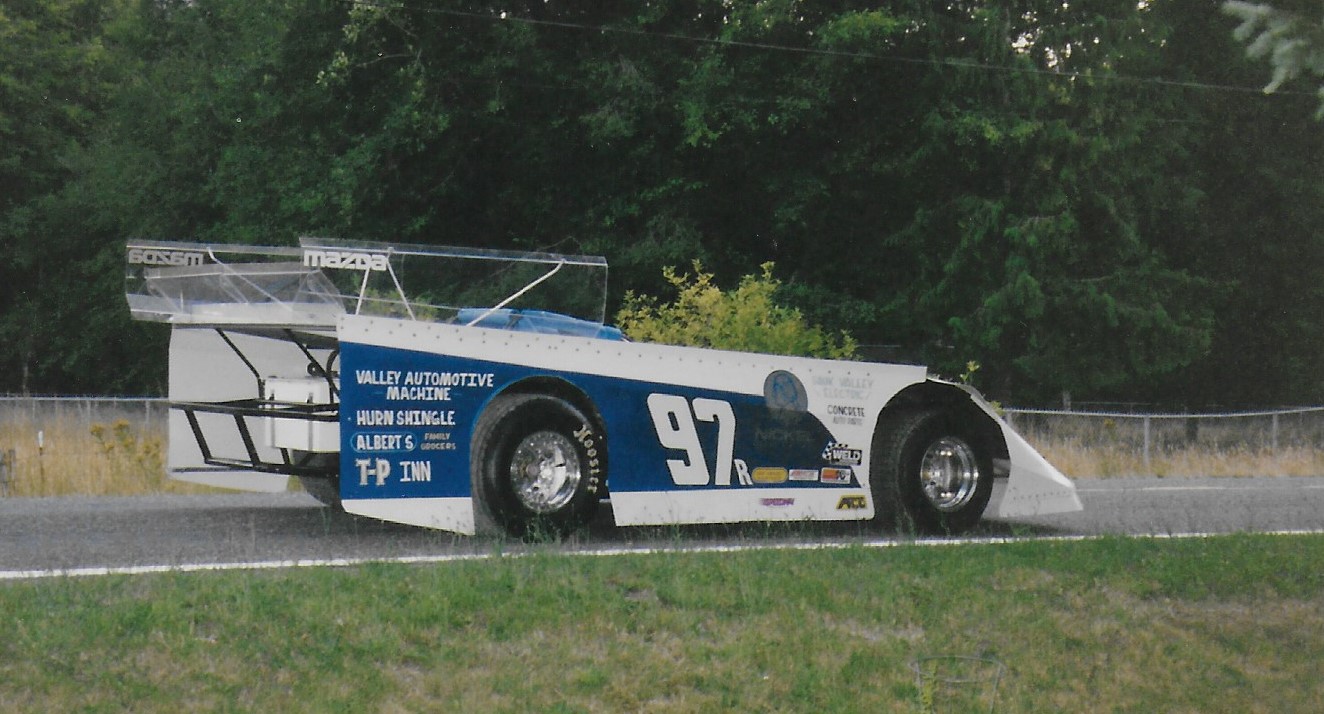
The Granny's SpeedShop Double Engine Dirt Latemodel
Powered by two Mazda 13B Rotary Engines
The Granny's SpeedShop Double Engine Dirt Latemodel
Powered by two Mazda 13B Rotary Engines
How many times have you heard someone say that they were going to build their own 4 rotor engine, and that they heard it was as easy as stacking the rotor sections of a coupla engines together?
Well here's a 4 Rotor I built, but it's the result of a couple years of
brainstorming and several thousand cans of RC Cola. The following is a brief summary describing what worked for me.
Both the engine and the car were specially designed & fabricated by myself, and burned up a couple years worth of free, and increasingly not so free, time. Eventually, growing demands on my time forced me to cut back on the long hours the racing program consumed. After a while, I found myself dreaming of a more conventional power plant. One that I could actually BUY parts for, without having to spend endless hours modifying before I could actually use them.
After some damage from a ripped off oil cooler line, the 4 rotor was replaced with an alky burn'n small block Chevy.
The engine design uses modified 13B eccentric shafts, and the two engines are joined by a custom made 3/8" thick aluminum adapter plate.
Removed from the front of the rear
engine are the front cover, oil pump, thrust bearing, counterweight, water pump, etc. Pretty much
wiped clean with the exception of the stationary gear and modified rear ecc. shaft. The 3/8" plate
bolts to the rear engine first, as internal bolts are needed to seal passages exposed when the front cover is eliminated from the rear engine.
A round donut shaped pilot ring was machined, which lightly pressed into the recess in the exposed front
stationary gear on the rear engine, and into the seal groove of the rear stationary gear of the front
engine. This pilot ring served to accurately align the front and rear engine's eccentric shaft bores, while allowing the e-shaft coupling to pass thru it's center. O-ring grooves in the pilot ring seal the front engines' rear stationary gear to the adapter plate, preventing oil leaks from inside the front engine's rear housing.
The 2 lower exposed (outside bottom) tension bolt holes are bored out and the stock bolts
replaced with very long bolts that go thru both engines, to pre-tension the lower part of the
engine, as I used only front and rear motor-plates, and no mid-plate support.
At the heart of the design is the coupling, which has to take a lot of abuse, yet remain small enough to fit thru a main
bearing to allow assembly. The coupling design
requires welding up the eccentric shafts (or building new shafts from scratch), which lengthens the full diameter portion of the shaft adjacent to the main bearing journals, so that the coupling can be machined into them. It is a tapered/pinned design that requires a draw bolt passing thru the bored out center of the front ecc.
shaft, threaded into the male half of the coupling (which is machined into the rear e-shaft), to draw the two ecc. shaft tapers together. The tapered portion
was about 1-1/2" long, with a series of (12) 3/16" dia. x 2" long aluminum pins arranged in a circle
about the taper parting line. As the pin holes are bored parallel to the e-shaft centerline, the parting line passes thru the pin at an angle, with 1/4" of each end of the pins firmly rooted in each of the shafts. The drawbolt thru the bored out center of the front e-shaft pulls the coupling together, and allows the front engines' thrust bearing to work for
both shafts.
Because the design removes what would have been the 2 middle counterweights, the
two engines were indexed the same (#1 rotors for each fired at the same time). This puts the two
middle eccentrics 180 degrees (in rotation) from one another, thus canceling the need for center
counterweights to maintain balance.
For the oil pump, I use the big oil pump on the front of the front engine, which feeds both engines, and modify the
drive ratio. By machining off and welding the toothed part of another oil pump sprocket onto the
eccentric shaft sprocket, it is possible to drive the oil pump at twice speed (1:1 instead of 1/2 speed), which roughly doubles the volume. The special drive chain required
is made from parts of 2 chains put together, as I could not find a source for the odd pitch chain.
A separator/de-airiation plate was made that fit across the entire bottom of the assembled
4 rotor, which helps seal the area between the engines for the full length, baffled and gated
custom built oil pan. A special larger pickup tube is made and the oil circuits "ported" to ease
the demands on the pump.
The water pump housing is modified so that the output can not
flow into the front engine from the front housing, but instead is re-directed into an external distribution manifold. From here, the coolant is split and directed into the top of the center housing of each engine. The modified rotor housing coolant flow
is into each center housing from the top, clockwise (from the front) around to the top on the right
side, cooling the combustion side of the engine first, then to exit ports that return the coolant to the radiator. No thermostat is used, only center housing outlet restrictors
to regulate coolant flow rates and engine temperature.
For the ignition system, my 1st design fired only 1
plug per rotor, and allowed using the normal point type distributor. Points were adjusted to fire
leading/trailing at the same time, with leading plug wires going to the front engine, and trailing wires
to the rear. A more modern ignition would be a direct fire using double posted "waste spark" coils,
one post for the front engine, one post for the rear. 4 coils would be used.
Starting the beast was
harder using 1 plug per rotor, so a 24v
starting system was used. The added voltage increased cranking speed, but the starter would overheat at anything
over 20 secs.(melted the solder in the brushes). A system that uses 18 volts cranks almost as fast,
as is not nearly as hard on the starter. If you use both plugs per rotor, the 18v system will work for
you.
During the duration of the project, the couplings experienced no damage at all. The draw bolt, which I felt would be the first external indicator of failure, maintained it's assembly torque with no sign of any loosening. When the engine was finally torn down (after an oil line was torn off during a race), the coupling and all it's components looked like new.
As proof of this, when the engine was assembled, the coupling pins and taper was coated with Loctite, which I felt would fill any minor discrepancies, and improve the strength of the coupling. Upon disassembly, the shafts were quite hard to separate, as the Loctite bond was still intact.
By joining the two engines as I did (using only 1/2 the normally required flywheel
and counterweight mass), the engine rev'ed much faster than a single engine by its self. Although
the exhaust note might be more pleasant if the engines were phased 90 degrees from one another
for an even firing order, the reduced mass and synchronized peak torque pulses make for less
stress on the coupling, and the reduced rotational inertia over that of two separate engines far
outweigh any performance advantages of the smoother sounding 90 degree firing order.
In the form shown here, output was around 550hp. Turbos were not allowed, so plain 'ol low octane pump gas was used. Race gas seemed to hurt power and make the headers glow. Thought was given to increasing the compression ratio by filling in the depressions on the rotor flanks, either by metal spraying them or bolting on some pieces of metal, but it was never done. We had planned to slip in some nitro, which would have helped with the relatively low compression ratio, but never got around to it.
By using the tapered/pinned design, the loads on the coupling are effectively spread out over a much larger cone shaped area. Less stress concentration, than what would have been present with any other type of useable coupling we could dream up, was an added bonus. All this in such a compact and relatively inexpensive design.

an addition featuring a description of the coupling making process, and a few of the other key components, including some dimensions taken from some old notes from the build in the early 1990's (before we had a computer or digital camera)...
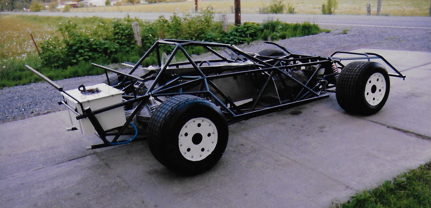

From here, you can see what can be a somewhat puzzling rear suspension. The basic design is a 4 link, in conjunction with an adjustable watts linkage, but here's where the dirt cars can get different. The 4 link brackets are not welded to the axle tubes, but allowed to rotate on greasable sleeves. This allows the rear axle to rotate in each sleeve independantly, eliminating the binds from their linkage. The axle housing rotation is controlled by a torque control rod attached to the aluminum plates atop the Quick Change centersection. The other end of the torque rod is attached to a spring and shock controlled "reaction arm", anchored to the chassis just to the right of the steering wheel. Barely visable is the blue specially made minature coil-over shock that controls the reaction arm. The reaction arm controls the wind-up of the rear axle, providing a degree of cushioning to help maintain traction over the rough and sometimes slick dirt track surfaces. The initial angle of the rod produces chassis lift to plant the rear tires on accelleration, but as the miniature coil-over is compressed, the angle levels out, reducing the vertical bind that an angled rod might otherwise have on the suspension travel. It works in reverse during de-celleration, controlling the initial pitch when the rod is closer to horizontal, then gradually increasing in angle to add squat to the rear.


The transmission is a hand fabricated unit, featuring only direct drive and neutral. A small multi-disc motorcycle clutch in the countershaft is used only to get the car rolling. Engaging dog ring on the mainshaft allows power to pass directly thru, bypassing the clutch. An aluminum flex plate, mounted on two bearings and one-way clutch, supports the ring gear. The one way clutch allows the starter to start the engine, but after the engine starts, it is no longer required to spin the flex plate. The result is the car could start and drive onto the track as per the rules, but didn't have to pay the penalty of the extra rotating mass of a conventional multi-disc clutch and flywheel.
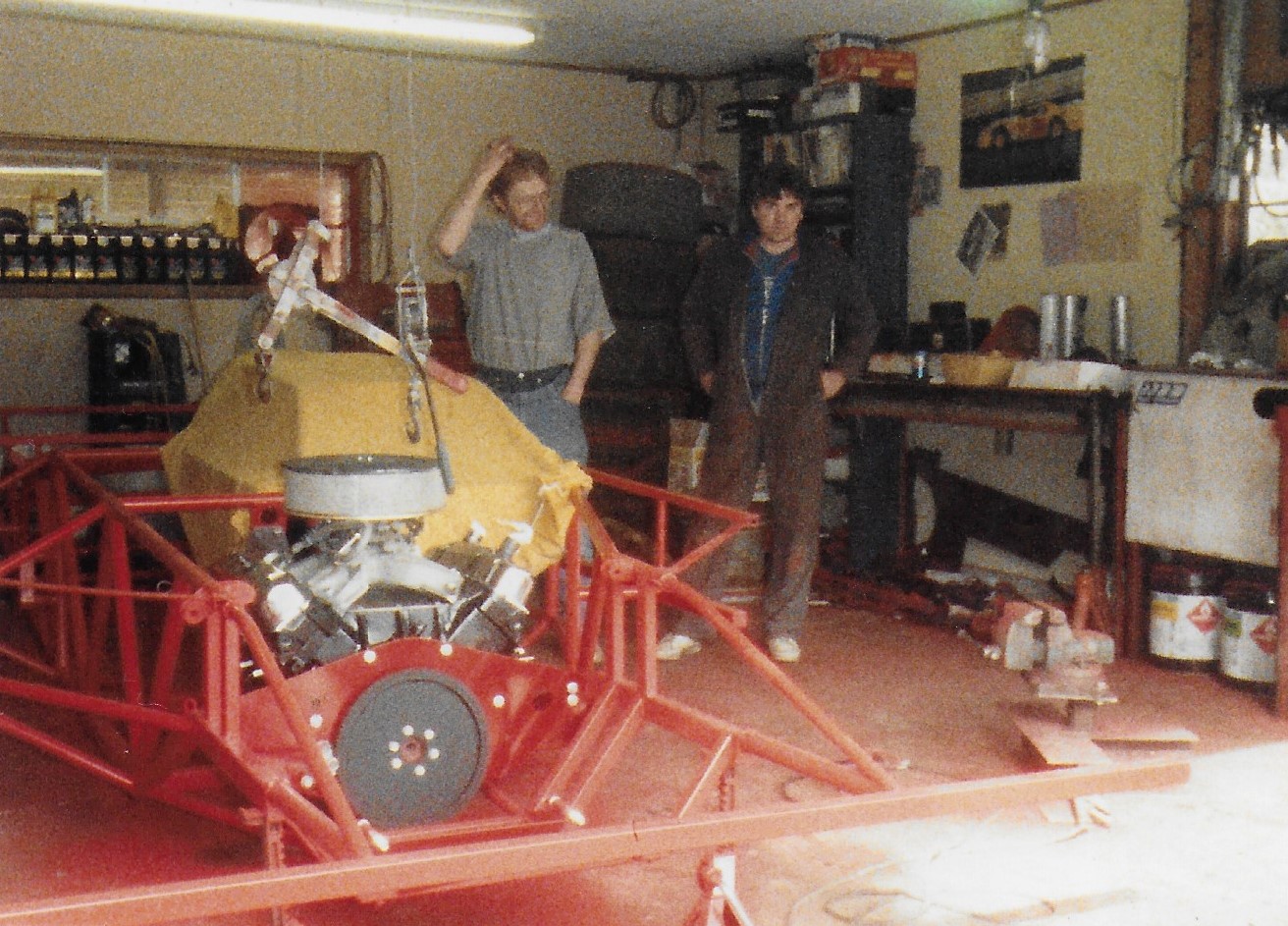
This one was built to beat an engine setback rule. The entire BB Mopar engine was reversed in the chassis, placing it's water pump, distributor, timing gears and oil pump on the "rear" of the engine, and only a lightweight ring gear and starter on the front. The net effect was like an additional 4" of engine setback. The mandated setback was 10-1/2" maximum from the upper balljoint centerline to the center line of the #1 sparkplug hole.
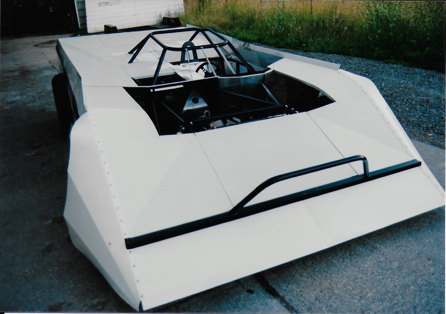
Here it is in running condition without the body...

As far as I know, this was the last Big Block Mopar car to win a feature at Skagit Speedway...

Here's a closer look at the little home-made transmission that's used in the backwards engine car, same one that was later used in the 4 Rotor car. Tha aluminum cover on the right of the pic is the hydraulic cyl that was used to apply the motorcycle clutch that was located in the countershaft. The long rod extending from the right side is the spring loaded shift rod, which is basically moving a dog ring slider to engage direct, bypassing the countershaft clutch for racing. The input shaft was driven off of a splined hub that was bolted to the BB Mopar's balancer. The Balancer got 2 more "keys" added between it and the crank snout to prevent shearing. A small fabricated bellhousing mounted the transmission to the front (or rear?) of the engine in the picture above, but it was originally mounted back 18" farther to the chassis and used a really long input shaft.
