website:www.grannysspeedshop.com
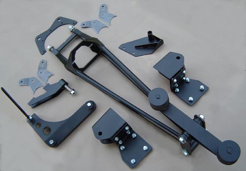
GSS Torque Arm / Solid Axle Conversion System
CLICK HERE for TASA conversion install FAQ
(TA/SA conversion)
'86-'91 RX-7 / Ford 8.8 DIY Kit Installation overview
Tools & Equipment Required
Tools...
Equipment...
Supplies...
Preparing your housing...
Proper prep of your housing depends on your plans for it. If you are not narrowing the housing, prep will consist of cleaning the outside, cutting off the old suspension brackets, and grinding off the remaining weld material from the axle tubes.
Measuring and cutting your axle tubes...
If you plan to narrow your rear, prep will be quite a bit more involved. So involved, that we recommend that the housing get completely dis-assembled. Remove the rear cover, and mark the bearing caps to prevent later mix-ups or confusion as to their correct position. Then remove the caps and pry out the differential, taking care to keep the bearing races and pre-load shims in their correct positions. At this point, we usually just run a wire thru the center of the diff's bearing bores to keep the spacers and bearing races in their proper place, tie the ends of the wire together, then place the diff in a box with the bearing caps, bolts, center pin, and c-clips for temporary storage. If the housing already has the gears that you plan to use, the pinion can stay in place. If you are changing gears, strip the pinion out as well.
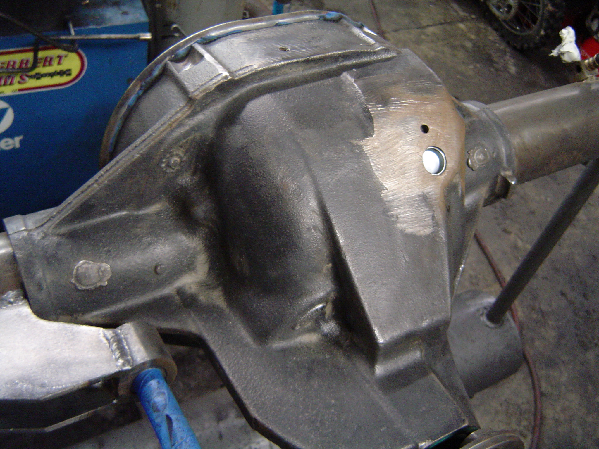
If your housing is from a truck and has the big ugly ABS sensor and guard lugs protruding upward from the front/top of it's center case, these will need to be removed. Remove the ABS sensor and drive a 13/16" expansion cup coated w/ loctite into the empty ABS sensor hole, driven in all the way down until it is flush with the inner surface of the case above the ring gear. Then use a sawzall or cutoff wheel in a hand grinder to remove the large part of the guard lugs, followed up by cosmetic blending with a hand grinder. Be careful not to get carried away with the cosmetic blending, as there are contoured areas inside the top of the case where excessive grinding on the outside can go all the way through, create a hole, and ruin your case.
Here's a list of recommended tools and equipment recommended for a sucessfull installation. All are not necessary, as you may come up with alternative ways to get it done, but this will give you a general idea of what you are in for...
...basic hand tools, both metric and SAE
...measuring tape
...string or plumb bob
...level
...3/8" drill bit
...1-3/16" hole saw
...5/16 nc tap
...0-250 ft/lbs torque wrench
...(2) magnetic triangles for weld positioning
...(4) jack stands for car
...(2) jack stands for rear axle
...personal safety gear such as gloves, safety glasses, etc.
...die grinder
...1/2" hand drill
...oxy/act torch or plasma cutter (for removing old brackets)
...4-1/2" hand grinder
...150amp MIG or DC welder & safety gear
...band saw or chop saw (for narrowing axle tubes)
...alignmet fixture (for re-welding narrowed axle tubes)
...blue Loctite
...red Loctite
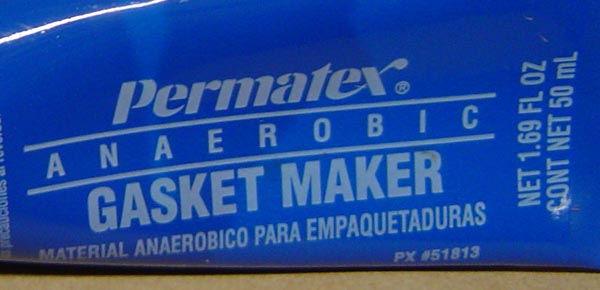
...anaerobic sealer such as Permatex PX# 51813 (for rear cover)
...paint for rear housing / brackets
...penetrating oil
...chalk
...gear oil
...friction modifier (for TracLoc or other clutch type limited slips)
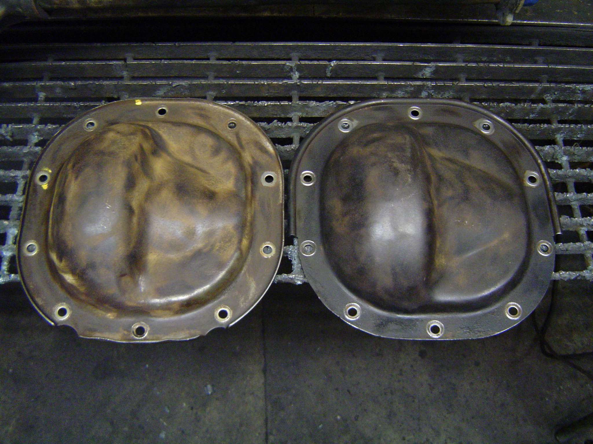
The housing below on the left shows the ABS sensor and it's guard lugs, the one on the right has had it's sensor removed, the hole plugged, and it's guard lugs have been removed. A sawzall followed up by a hand grinder will get the job done...

Section the axle tube after the old brackets have been removed, as it is easier to clamp the tube in a bandsaw without brackets getting in the way. We recommend making the first cut at a point exactly 2-1/2" inboard from the outer face of the axle's flange. This is a point far enough in-board to get the effects of welding away from the machined bearing fits, and still allow us enough room to install all the brackets before welding the tube end back on. Next the remaining axle tube can have a section removed to achieve the desired width. Do not weld the tube ends back on at this point. Wait to weld the tube ends back on last, after all the other brackets have been finish welded, to insure accurate housing alignment.
If you are planning for using the original RX-7 brakes on a narrowed rear, you will need to design in the proper brake offset. Brake offset directly effects how the caliper is positioned over the rotor, side-to-side. We plan for using a flat 1/4" thick adapter bracket if possible. The basic idea is to position the caliper correctly over the rotor to allow for plenty of caliper movement, allowing for both new pads and for enough travel to compensate for movement of the caliper as the pads wear. Since the axle position relies on the differential for it's retention, slight variations in axle position may occur as some diff carriers must be shimmed differently to achievs the correct backlash, in turn effecting the in/out location of the axle. When we spec a narrowed rear, we shoot for a slightly larger brake offset dimension, making it easier to deal with a worst case stack-up of tolorances. If the offset spacing is slightly larger, minor shimming of the caliper bracket can align things up perfectly. If the spacing is too small, machining may be necessary to correct it. If you try to duplicate the brake offset that your original RX-7 rear, you will likely be safe, but err on the side of larger.
Here's some facts that you may find handy if you are trying to calculate overall housing width, axle length, axle tube length, and brake offset, trying to come up with something that works for you...
...the 8.8 pinion shaft is offset 9/16" to the right of the cast housing's center.
...the cast centersection of an 8.8 is very consistantly 16-3/8" wide.
...the 8.8's diff's center pin is centered in the cast centersection.
...both axles will extend an equal distance into the 8.8 cast center.
...the 28 spline diff uses a 3/4" dia center pin.
...the 31 spline diff uses a 7/8" dia center pin.
...8.8 axles are measured from outside face of lug flange to the tip of the c-clip button.
...AF/AF width is the sum of right axle length, left axle length, and center pin diameter.
...axle tube length is measured from the outside face of it's outer flange to the edge of the cast center section.
...brake offset is measured from the outside face of the axle's lug flange to the outside face of the axle tube's flange.
...the brake offset dimension needs to be correct for the brakes used to place the caliper correctly over the rotor.
...axle tube length can be varyied within reason to achieve a desired brake offset.
...axles of the same length and spline count are interchangable between the Ford 7.5" rear and the Ford 8.8.
...all Ford 7.5 rears came with 28 spline axles.
If you plan to order custom axles for your narrowed 8.8, here's some info that may be useful...
...8.8's from passenger cars, Rangers, and Aerostars use the smaller passenger car sized axle bearings / seals / 28 spline axles.
...8.8's from full size trucks, Explorers, and vans use the larger truck sized axle bearings / seals / 31 spline axles.
...order the axle's flange dia, lug pattern, lug hole dia, and center pilot dia for the brakes you plan to use.
...28 spline axles use a c-clip button that's .250" thick.
...31 spline axles use a c-clip button that's .300" thick.
...28 and 31 spline differentials can be interchanged as long as the appropriate axles are used.
...axles can be ordered with 31 splines and the smaller passenger car sized wheel bearing diameter.
Recommended maintenance...
After the dirty work is done on the outside, maintenance should be performed. Remove the rear cover and clean the gasket surface. Does your TracLoc need new clutches? Now's the time to do it. Also be sure to run a 5/16" nc tap down into all 10 rear cover bolt holes to clean out any debris or leftover sealer that might prevent the new bolts from tightening down properly. Blow the holes out with air when done.
Installing lower link brackets on your axle tubes...
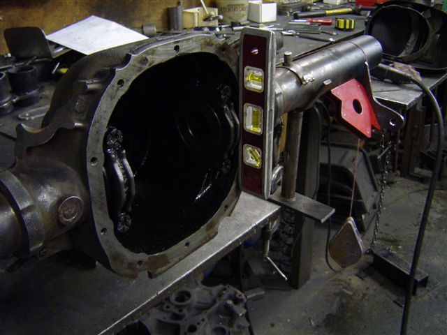
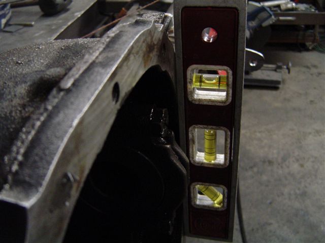
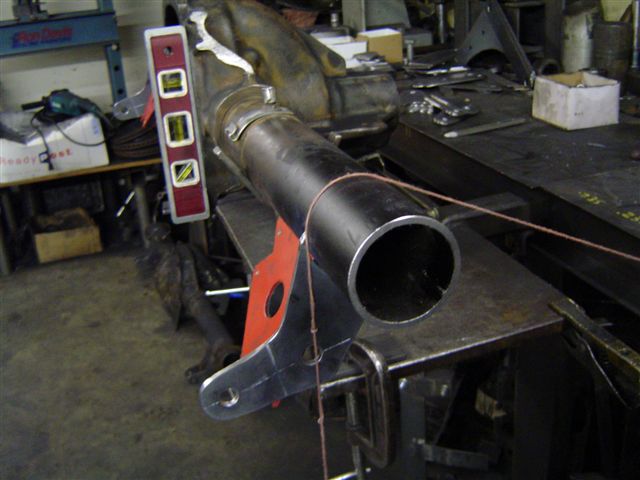
We recommend that you prepare for installing lower brackets onto your axle tubes by first leveling your housing. The setup we use consists of a pair of "V" shaped saddles to support the axle tubes, along with an RX-7 scissor jack under the housing's nose, below the front pinion bearing. The scissor jack works very well for our purposes, as fine adjustments can easily be made. Our goal is to get the housing's rear gasket surface to be "plumb"...
 .
.
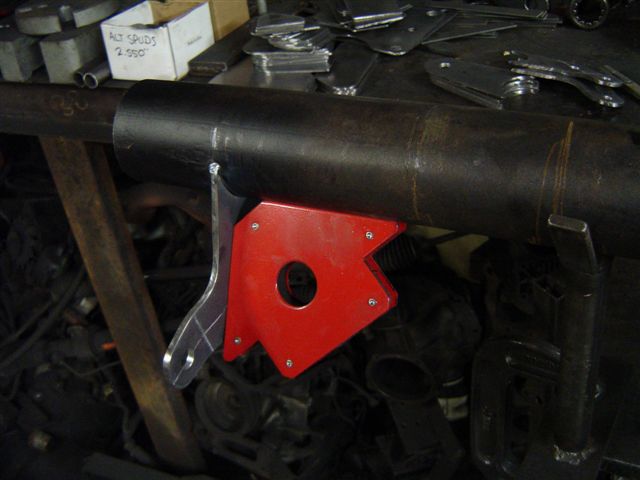
We use a pair of magnetic triangles to hold the brackets in position before welding. Using these allows us to easily measure and re-position brackets as necessary, greatly simplifying the task. Their laminated / triangle construction works very well for this purpose, as their shape automatically squares the bracket with the axle tube while holding it in place prior to tack-welding. These magnetic triangles can usually be found in a welding supply store for around $20./ea.
We locate the attachment points for the lower/inner plates next...
The spacing between the lower control arm's rear mounting points does not have to be the same as the appx 42" spacing of the front brackets...we prefer to move the rear points in slightly to appx 40-3/4" c/c width at the rear. This puts the rear/inner mounting plates about 38-1/2" apart, evenly spaced from the ends of the axle housing. Be careful to use a plate that has it's shock mounting hole stepped in the correct direction.
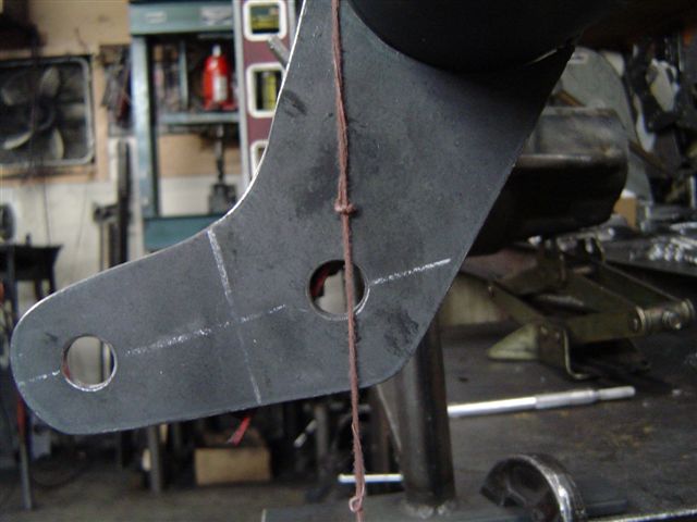
Next, we position the proper location of the lower control arm's rear mounting hole. If your axle tube diameter was 3", the string would pass thru the center of the hole. The axle tubes in the pics are about 2-3/4" dia, so the string is about 1/8" forward of the center of the hole.
......For a 2-3/4" axle tube diameter as shown, the string should be 1/8" forward of the hole's centerline.
......For a 3" diameter axle tube, such as some 9" Ford or 8-3/4" Mopar, the string should be centered with the hole.
......For a 3-1/4" diameter truck/Explorer axle tube, the string should be 1/8" to the rear of the hole's centerline.
 .
.
After both inner plates are tacked into position, the outer plates can be located. We use a machined spacer to position the outer plate properly, but you can easily use a stock rear lower control arm from a 1st gen '70-'85 RX-7 as the spacer, which is what the brackets are designed for. The inner plates/bolt/spacer will now serve to position the outer plates correctly.
With the bolt/spacer still in place, finish weld the outside of each bracket to it's axle tube. We also place a weld appx 1" long on both inside corners of each bracket.
Installing the pivot bracket for the watts linkage...
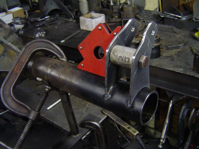
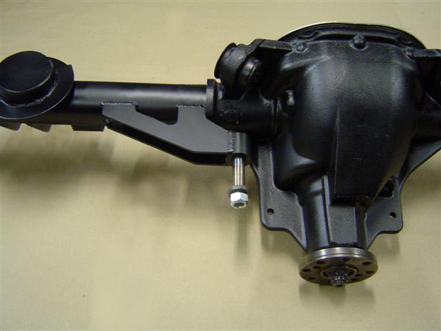
To position the watts pivot bracket, we position the stud's centerline parallel with the pinion's centerline. The bracket's edge is placed on the axle tube, against the shoulder of the cast diff housing, then welded to the axle tube in 4 places (2 top, 2 bottom).
Installing the sway bar brackets onto the axle tubes...
Positioning and welding axle tube end housings...
We try to wait until the everything else on the housing has been welded before we install the axle tube ends onto the tubes. The reason is that all cutting/welding has at least some effect on the axle tube's straightness. After the rest of the brackets are installed, we use a precision ground bar located off of the diff's side bearing bores to locate and ensure proper alignment of the axle tube ends.
Installing backing plates or caliper brackets...
Use only new 3/8" grade 8 fasteners torqued to 45ft/lbs to secure our caliper brackets to the 8.8 rear.
Housing assembly, final prep, & paint...
Modifying and installing the rear cover...
Before installing your 8.8's rear cover, it will need to be modifyied to fit properly with the torque arm's rear mounting plate. We use a plasma cutter to quickly trim away the lip from the lower part of the cover's flange, but it can also be ground down with a hand grinder or trimmed w/ an oxy/acytelene torch.
The cover on the left is stock, the one on the right has had it's outer "bead" removed from it's lower half as described above...
If you are installing a chrome rear cover, it's gasket surface should be roughed up so that the sealer can get a proper "bite" on the smooth cover. We lightly sand the gasket surface on a belt sander to rough-up the chrome for a good bond/seal. We don't want the rear cover moving around, causing leaks.
Instead of using a gasket to seal the rear cover, we prefer to use a form-in-place anaerobic sealer made by Permatex, PX# 51813. Without a gasket, we get intimate metal-to-metal contact that locates the rear cover to the housing more rigidly. Apply the sealer in a bead similar to that shown below...
 .
.

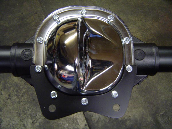
Fasten the rear cover and rear bracket for the TA to the housing using the 5/16" gr8 flange-loc bolts supplied with the kit. There are (5) short bolts and (5) long bolts. Be sure to use the shorter bolts in the upper holes. The longer bolts are used on the bottom, the longer length necessary due to the additional 3/16" thick TA bracket. Run the cover bolts down evenly, followed up by torquing them down to 26 ft/lbs.
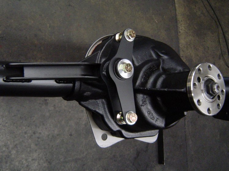
Fitting and installing the Torque Arm...
Our Torque Arms are designed to fit the nose of your differential very closely. It was fabricated and hand fitted to an actual housing in our shop to insure a snug fit. Although not required often, minor differences in castings may require additional hand fitting of the torque arm's front plate. If your torque arm fits too tightly around the pinion housing, a few seconds with a die grinder or dremel tool w/ a small carbide cutter will provide a quick remedy.
After the Torque Arm is in place on the housing, bolt it to the rear bracket using the (2) 3/4" bolts and flat washers supplied. The bolt fit will be very snug, so be careful to start them straight. Tighten them up evenly. Follow up by torquing them down to 100 ft/lbs.
Removing your RX-7's IRS and subframe...
Prepare for rear subframe removal by raising the car about 18" off of the floor, properly supported at the OEM jacking points. Notched jackstands are preferred to prevent damage to the welded seam.
...After safely and securely supporting the car, the remove the rear tires.
...Remove any exhaust system components in the area of the rear subframe.
...Remove the driveshaft.
...Remove the brake calipers from the hubs, leaving the hoses and e-brake cables attached, then hang the calipers from the body with wire to prevent damage to the hoses.
...Remove the rotors from the hubs. Save them for possible use later.
...Remove the bolts attaching the rear shocks to the lower control arms.
...Remove the bolts attaching the sway bar end links to the lower control arms.
...Remove the lower bolt on the vertical strut near the driver's side of the center housing.
...Support the subframe by placing a floor jack under it's center.
...Remove the two large nuts, one on each side of the differential housing's "wings". The diff assembly should drop onto the subframe/jack.
...Remove the bolts from the two support struts extending away from the forward mount washers.
...Slowly remove the two remaining nuts from the forward mounts.
...Slowly lower the entire subframe and remove it from under the car.

...The original subframe, diff, axles, driveshaft, etc are no longer needed. The whole thing's not worth much if it's 4 lug. If it's either '86-'88 5 lug, 3.90, or even T-II, you should be able to sell it without much trouble.
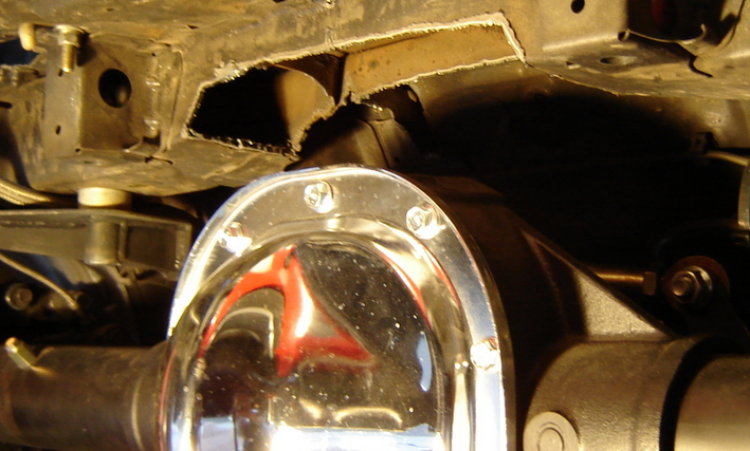
Repositioning your RX-7's fuel lines above the rear housing...
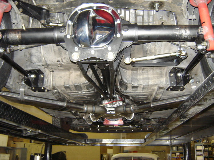
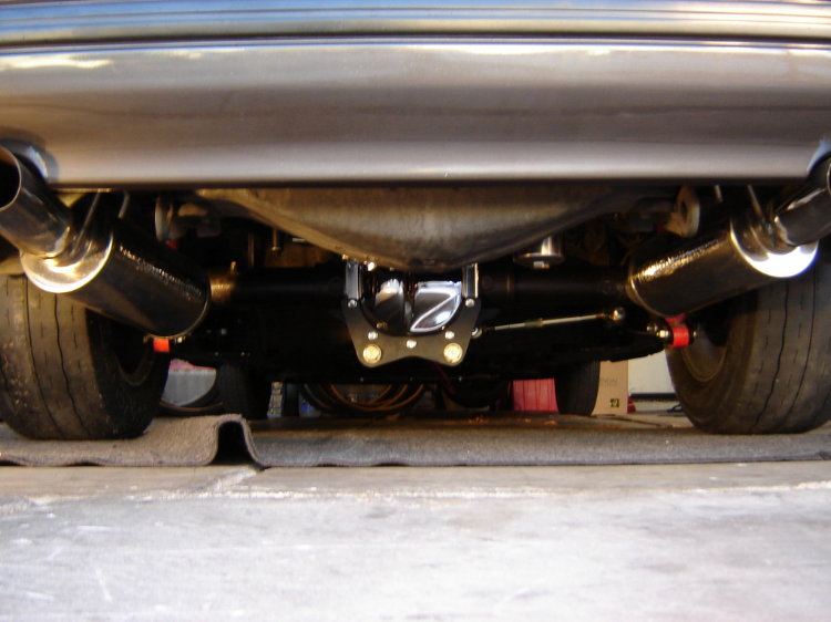
The picture below shows how the RX-7's fuel lines will run directly over the 8.8's centersection (click on the right pic for a larger close-up view). We don't want to take a chance on a collapsed or damaged fuel line, so now's the time to move them.
 .
.
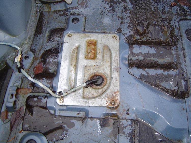
If you want access to the tank end of the rubber hoses, you can get access to the top of the tank (and fuel pump) via a removable cover, located under the carpet (over the tank), in the rear hatch area. The area in the pic is located under the rear hatch carpet, just inside/back of the driver's side shock tower.
Installing the lower control arm's front pivot boxes...
Temporarily pull up the carpet and padding from the floorboard area behind the seats.
Slide the front pivot boxes onto the front studs formerly used to attach the subframe. Thread a nut onto the stud for the purpose of temporarily holding it in place.
Using the installed pivot boxes as a template, mark the remaining (16) 3/8" holes (8 per side) for drilling.
Remove the pivot boxes and drill the marked holes.
Re-install the pivot boxes.
Install the inner backing plates, bolts, and nuts. Torque them to 25 ft/lbs.
Re-install the carpeting.
 .
.

Installing the Torque Arm's front yoke assembly...
Next, it's time to drill some large holes for the Torque Arm's front yoke. The front hole is located in the center of the tunnel, near the rear of the e-brake's mounting plate. The rear hole is located in the center of the tunnel, centered in the top of a raised rib. The center-to-center distance between the holes should be 12-3/4". Draw a large "+" thru the center of the holes, so that as the hole is being drilled, you will be able to make sure that the hole is not walking off-center.
Drill or die-grind both holes to a diameter of 1-3/16", the size of the rubber puck's pilot diameter.

Position the upper rubber pucks, pilot tubes, bolts, and 3" dia flatwashers over the holes, with the rubber pilot extending thru the hole. The front puck has a notch machined into it, which provides clearance for the e-brake bracket's rear bolt.
 .
.
Place the rear lower rubber puck into position from the bottom side of the tunnel, over the rear bolt, with the machined slot in the rubber facing down with the e-brake cable passing thru the slot. Push the puck up onto the pilot tube extending down from above, which will hold it into place.
 .
.
Push the front lower puck into position from below. Push the puck up onto the pilot tube, which will hold it into place.
 .
.

Install the remaining yoke assembly from the bottom, over the bolts. Using the 1/2" flangeloc nuts provided, tighten both bolts to 60 ft/lbs.
 .
.

Installing the driver's side watts anchor bracket...
Slide the large 1-1/2" dia x 5/8" thick spacer onto the large stud formerly used to hold up the passenger side of the stock RX-7 diff housing. This spacer fills the space above the bracket, shimming it down on the stud, aligning it with the flat surface of the frame rail.
Next slide the watts bracket over the same stud, while aligning with the 2 holes in the chassis. Install the chassis bolts, tightening them to 45 ft/lbs.
 .
.

Next install the flat washer and nut over the stud, and tighten to 65 ft/lbs.
Installing the passenger side watts anchor bracket...
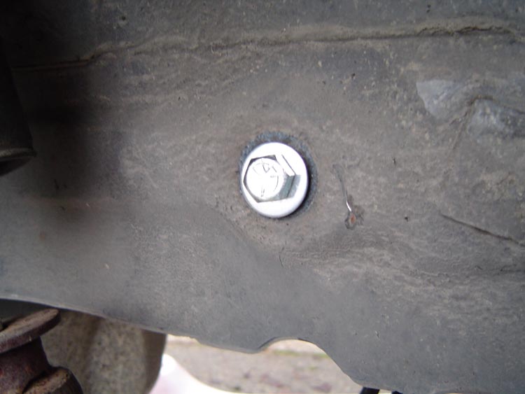
The "L" shaped passenger side watts anchor bracket mounts thru the bottom side of the floor pan, in the area directly below the pass side storage bin. The bracket mounts to the floor pan at two points, and to the sheet-metal "frame rail" above using a bolt-on vertical stabilizing strut.
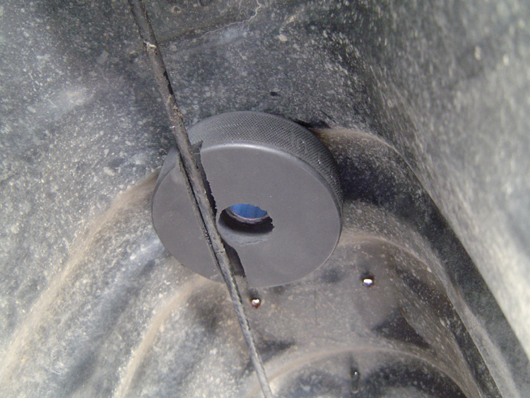
...For the inner mounting point, we use an existing "drain" hole (actually a locating hole for the factory assembly jig), located inside the round cut-out in the matting, formerly sealed by Mazda with a large rubber plug. Remove the rubber plug, which is no longer needed.
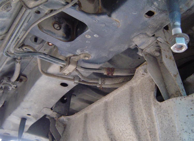
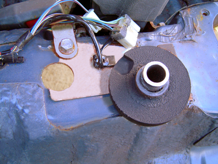
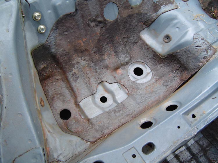
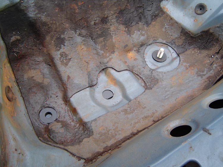
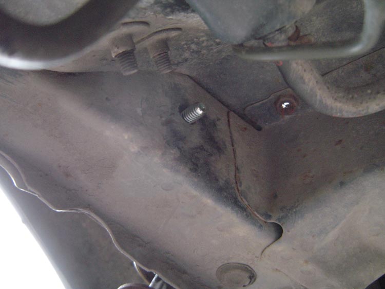
...For the outer mounting point, we enlarge an existing small hole (hidden under the matting), located about 10" to the pass side of the above mentioned "drain" hole, between the two "dimples" in the floor pan. This small hole needs to be enlarged to 7/16", the size of the hole thru the machined pilot insert welded to the anchor bracket. An enlarged hole is shown below, in the lower left side of the picture. The view is from the passenger side of the car, looking in thru the door opening, with the rear storage bins or rear seat removed.
The sheetmetal around the two holes is clamped between the bracket's machined insert and a heavy 1-1/2" dia machined "clamp-washer" installed from above. A 7/16" dia gr8 bolt/nut is used in each hole to provide the clamping force needed to securely locate the bracket.
Intall the bracket into the large inner hole first. Be sure the machined pilot fits into the center of the hole properly, then place the "clamp-washer" over the insert from the top, recessed side down. Install the 7/16" bolt thru the washer and bracket from the bottom, then install the locking flangenut on top. Temporarily tighten the bolt/nut to around 10 ft/lbs.
 .
.
Next we align the bracket's outer machined insert with the 7/16" hole we enlarged earlier. Place the "clamp-washer" over the insert from the top, recessed side down. Install the 7/16" bolt thru the washer and bracket from the bottom, then install the locking flangenut on top. Torque the bolt to 71 ft/lbs. Torquing the bolt will force the sheetmetal of the floorpan to conform to the stepped insert, insuring a perfect interference fit with no slop.
Finish torque the temporarily tightened bolt in the inner hole to 71 ft/lbs.
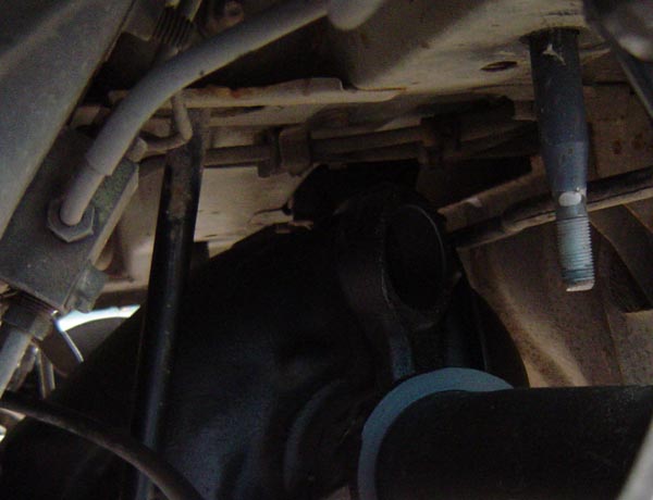
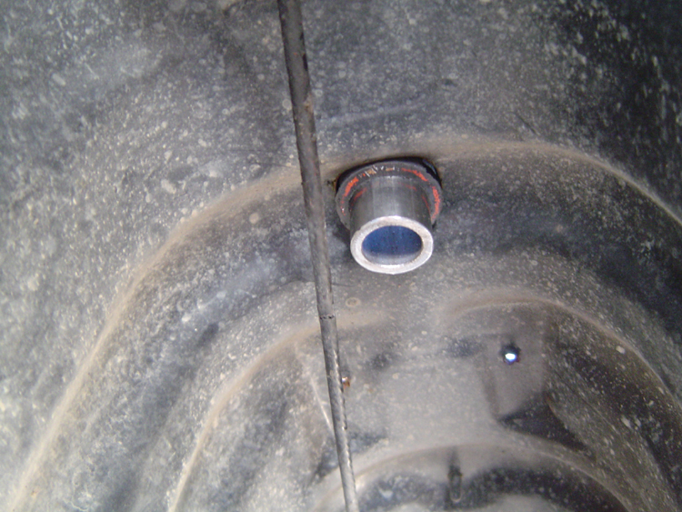
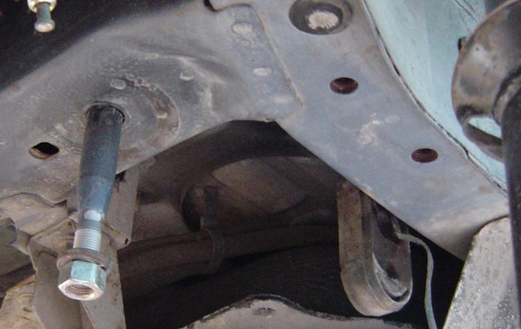
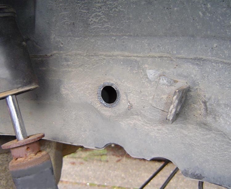
Next, we install the anchor stud for the bracket's support strut. Remove the rubber plug from the hole located just to the rear of the brake hose's chassis tab (center of pic below).
 .
.
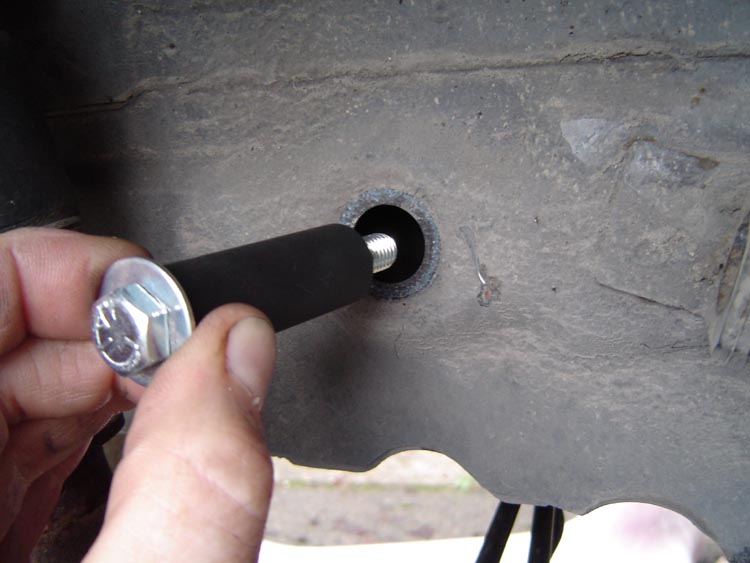
Fully insert the threaded end of the stud into the hole, thru into the inner hole, so that the threaded end comes out of the existing hole on the sheetmetal frame rail's inner side...
 .
.
Next install the strut bar's upper end over the threaded stud. Secure w/ the 3/8" flangeloc nut provided.
Secure the strut bar's lower end to the bracket's tab, using the 3/8" bolt, washer, and flangeloc nut provided.
Torque both upper and lower strut bar bolts to 30 ft/lbs.
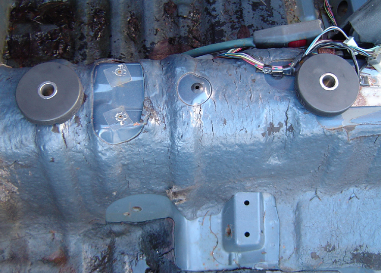
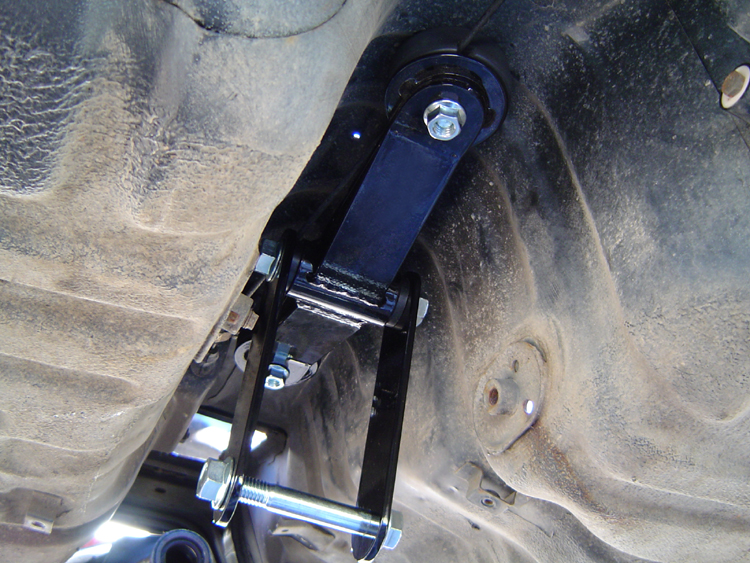
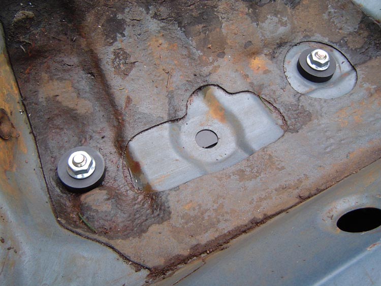
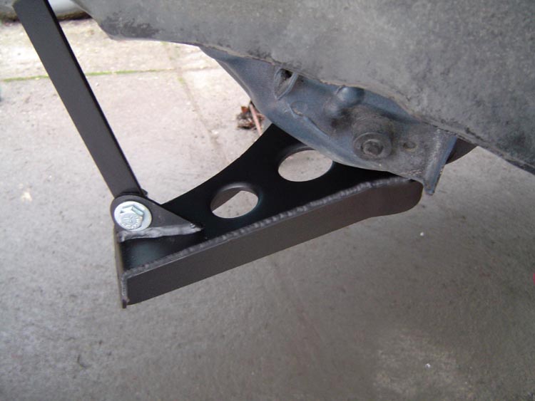
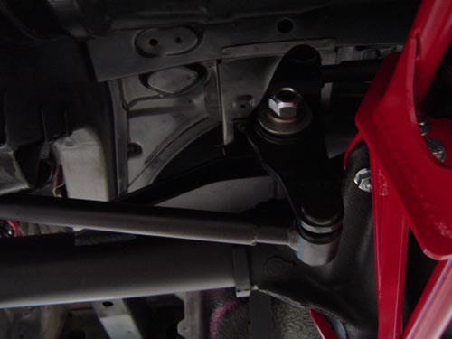
When installed properly, the passenger side watts anchor bracket should look like this...
 .
.
OPTIONAL- additional mods for lowered cars...
If your car is lowered, you will want more room for the 8.8 rear axle housing to move up into the body before it hits the chassis. Two areas will need modification, and it will require a little cutting/welding.
Lowering mod 1- the sheetmetal crossmember above the diff will need to be cut out for clearance. It can be plated back in with 16ga sheet, but most customers don't bother. The mods shown below were done with a torch, a cutoff wheel in a die grinder does a cleaner job almost as quickly.
Lowering mod 2- the stud that locates the driver's side watts bracket will need to be cut so that it does not contact the axle tube. We usually just trim it flush with the top of the bracket's tube, then weld the remaining end of the stud to the tube on the bracket.
Driveshaft clearance- Transmissions behind rotary engines are positioned higher in the chassis than those behind a piston engines. Due to this, lowered or rotary powered cars will want to reverse the rubber pucks between the nose anchor assembly and the top of the transmission tunnel, with the thinner puck on the bottom to move the nose anchor closer to the top of the tunnel, for additional driveshaft clearance. In an extreme case of a rotary powered car that has been lowered, a special low profile nose anchor assembly will be needed.
 .
.
Finally, 8.8 meets RX-7...
Slide the 8.8 rear with torque arm into place under the car. Use a couple of jack stands to support the axle tubes near their final location. Pull the nose of the torque arm up into place, where it can be temporarily supported by pinning it, with a bolt, to the yoke plates hanging down from the front yoke assembly.
If you are using the stock lower links from a '79-'85 RX-7, install them using their original eye bolts and nuts.
If you are using our larger rod-end style adjustable lower links, there are a few extra steps to ensure proper assembly...
Insert the spacer bushings into the rear shock's lower mounting holes, then slide the lower shock eyes into position between the brackets attached to the axle tubes. Install the bolts w/ washers & flange nuts, torquing each to 60 ft/lbs.
Installing the driveshaft...
This step is often overlooked, but before installing the driveshaft, be sure to grease both u-joints. Also, to protect the output shaft's rear bushing and seal, be sure to lube the slip yoke with some light oil before inserting it into the transmission.
Temporarily pull the bolt holding up the nose of the torque arm, allowing the torque arm's nose to be lowered for driveshaft installation. With the nose of the torque arm lowered, slide the driveshaft into the transmission.
Bolt the rear of the driveshaft up to the flange or yoke.
Pull the nose of the torque arm back up into position, between the two side plates hanging down from it's front yoke assembly. Slide the 5/8" bolt into place from the passenger side. Install the washer and self-locking nut. Torque the bolt/nut to 90 ft/lbs.
...adjust each bar so that both it's ends extend from the tube an equal distance.
...install the link on the car with the left hand thread end on your left when you are facing it. This will make it easier to remember which end has the left hand threads later when you are trying to make adjustments.
...Each rod end will be spaced to the center of it's bracket using two cone shaped spacers, one on each side of the rod end. The larger side of the spacers face away from the rod end, against the inside of the bracket.
...insert the gr8 bolt, washer, and nut thru the bracket, spacers, and rod end from the outside. Install a 5/8" flange washer on the inside, and torque to ????? Repeat for the rear ends of the links.
......If your 8.8 has a flange, torque the (4)12mm x 1.75 pitch (25mm long) pinion flange bolts to 60 ft/lbs ea.
......If your 8.8 has u-bolts, tighten them to a guesstimated 25 ft/lbs ea.

Installing the watts linkage and centering the rear...
If you are using the OEM watts linkage from a '79-'85 RX-7 on a standard width '86-'93 Mustang, your watts linkage's "bars" will need modification to properly clear and center the rear. The easiest way we have found is to simply cut the ends from the oem bars ans add custom "sleeves" to the center to correct their length and offset. We supply sleeves that are bored out to a slip fit over the cut-off ends of the stock bars, requiring only simple welding to complete the modification.
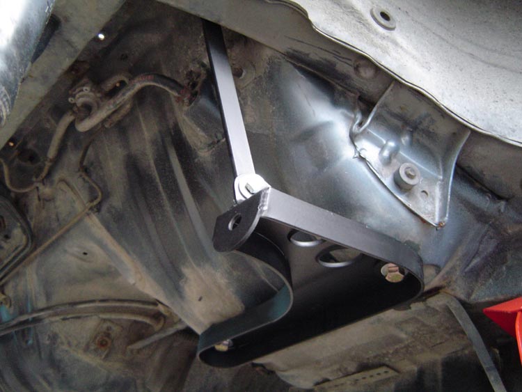
The picture below shows, installed, a stock watts linkage from a 1st gen RX-7. Note that the rods have been sleeved as described above...
If you are using our fabricated watts linkage, the supplied threaded bars are easily adjusted to center the rear under the car.

Below is the correct orientation of the watts bellcrank, the long arm is on the bottom, short arm on top. Both arms are offset from the pivot in the direction of the driveshaft...
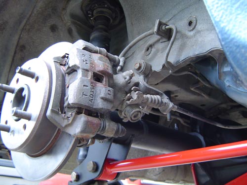
Installing the brakes and e-brake cables...
If you are using the original RX-7 brakes, this step is pretty basic, just bolt them up to the supplied brackets. Be sure to check for clearance between the rotor and any brackets or bolts that may come in contact with it.
Final inspection and safety check...
Periodic inspection and maintenance...
Keep a watch out for oil leaks from your rear, especially from it's rear cover. Not only can a leak cause component damage from low oil level, it also may indicate loose cover bolts that play a critical part in anchoring the rear of your torque arm.
 ...Click Here for Ordering Information...