
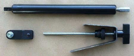
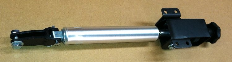
Above is a picture of the early version of our ClutchTamer Universal Kit.
At top is the hydraulic release cylinder. On lower left is our easy to install clamp-on clutch pedal bracket.
Lower right is the dash bracket, threaded extension rod, and Initial Hit Dial and Secondary Delay Knob.
ClutchTamer Install & Initial Set-up Guide...
This install and set-up guide is intended to make your ClutchTamer install quicker and easier. As you become more familiar with the ClutchTamer and how it works, you will undoubtedly form your own ideas about developing your own combinations of adjustments, and how to further refine them to work best for your specific set of circumstances.
Pre-Installation Requirements...
IMPORTANT- you must have a clutch pedal stop in place! A very important part of getting consistent launches is to have in place a properly adjusted clutch pedal stop. It's function is to insure that the slipper's rod is always pulled out exactly the same amount every time the car is staged, so that it can consistently delay the clutch's lockup.
NOTE-...if you are performing a custom installation, be sure to orient the cylinder with the shaft end (with delay knob) HIGHER than the cylinder end. This is to insure that the oil in the cylinder is self bleeding, as to keep any air pockets away from the internal metering circuit.
Step 1- Installing the Clutch Pedal Bracket...
Our clutch pedal brackets are designed to install by simply slipping them over your pedal's "arm", secured to the pedal by a simple pinch bolt. This allows you to easily slide the bracket up/down the pedal for proper positioning, which usually places the ClutchTamer's cylinder appx 5" to 5-1/2" below the clutch pedal's pivot point. Tighten the pinch bolt will secure the bracket's position on the pedal.
NOTE- Be sure to check for interference above the cylinder as the pedal swings thru it's arc, as the cylinder can be damaged if it comes in contact with a bracket or something structural.

Step 2- Install the ClutchTamer's Hydraulic Cylinder onto the Clutch Pedal...
Place the hydraulic cylinder into position under the dash, and secure it to the clutch pedal bracket with the provided attachment pin and retaining clip. Do not install the threaded rod onto the cylinder's shaft at this point.
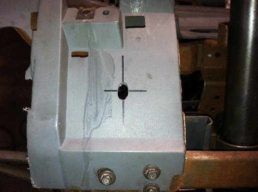
Step 3- Preparing the Dash for an "In-Dash" Style Slide Bracket installation...
Most OEM dash assemblies have a metal substructure. Remove the plastic cover from the lower dash in the area of the clutch pedal to reveal the metal substructure.
...locate an area inline with the clutch pedal where you would like to locate the ClutchTamer's control knob.
...drill a 21/64" hole where the cylinder's shaft will need to pass thru. Do not make the hole bigger at this time, as we are using it to temporarily locate the cylinder in it's correct position.
...place the threaded rod thru the 21/64" hole and screw it into the end of the hydraulic cylinder's shaft. The threaded rod should now stick out quite a bit from the dash, but do not cut it's length yet. The cylinder and threaded rod should now be very close to their installed position.
Step 4- Fitting the Dash Slide Bracket to the Dash Substructure...
NOTE- if you need to remove the plastic slide bushing from the dash bracket, it just "snaps" together. Simply slip a small blade under the rear "washer" portion, with a gentle pry it should snap free from the slide bushing. A small set of pliers can be used to "snap" the washer/bushing back together for re-install.
We provide a simple universal dash bracket that is made of mild steel. It has the basic shape that is needed in the center for the cylinder's shaft to pass thru, but the ends of the bracket that actually attach to the dash will require some minor fabrication to make them fit up properly to your existing dash substructure. Since the material is mild steel, it can easily be bent or hammered at it's ends to achieve a perfect fit. The proper orientation should have the slide bushing in the middle of the bracket perpendicular to the shaft that passes thru it, so that the knob and dial will contact the bushing's face evenly top/bottom/side/side. After you are satisfied with the Dash Bracket's fitment, remove it and place it aside while you further prepare the area for it's final attachment.
Below is shown an '87-'89 FOX Mustang in-dash installation...

Step 5- Enlarging the Hole in the Dash Substructure...
...to allow access to enlarge the dash hole to it's finished size, remove the threaded rod from the cylinder's shaft, and let the cylinder temporarily hang free from the clutch pedal bracket.
...Using a step drill, carbide bit, or rotary file, enlarge the hole in the dash substructure to appx 1" dia.
Step 6- Attaching the Dash Slide Bracket to the Dash Substructure...
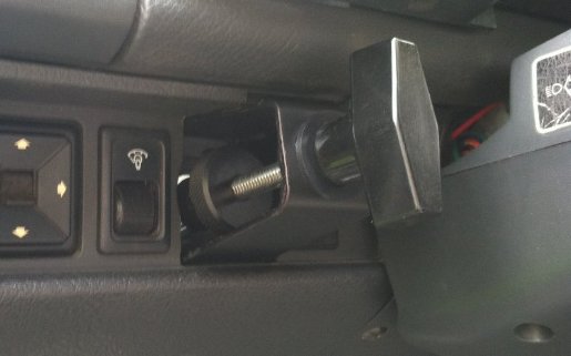
For final attachment, we like to spot weld the bracket to the substructure. As an alternative rivets or small bolts/nuts could also be used. If spot welding, be sure to take proper precautions to prevent fire and/or damage to electronic equipment. Below is shown a universal underdash installation...

Step 7- Trimming the Length of the Threaded Rod...
...re-install the threaded rod thru the slide bushing and into the cylinder's rod. Bottom it out in the coupler's threads, then secure it in place with the provided jam nut.
...screw the plastic Delay Knob onto the threaded rod until it's threads bottom out, then just slightly more until it is tight enough so that the Delay Knob can be used for turning the cylinder's shaft. At this point, the Delay Knob should seem to be sticking out way too far.
...rotate the Delay Knob counter-clockwise until you can feel the added resistance to rotation when it reaches the end of it's adjustment range. This point is what we call it's "0 Turns" adjustment.
...turn the Delay Knob clockwise to the "2 Turns" adjustment position, then measure the distance between the Dash Bracket's Slide Bushing and the flat area on the Delay Knob. Write down this measurement, this will be the "cut amount" that will be trimmed from the long end of the threaded rod.
...remove the plastic Delay Knob from the threaded rod.
...remove the threaded rod from the cylinder's shaft.
...note that the threaded rod has a groove milled into it appx 1" from one end. DO NOT cut this end of the threaded rod, we call this end the "short" end. Trim the "cut amount" from the "long" end of the threaded rod, take care not to damage the rod's threads.
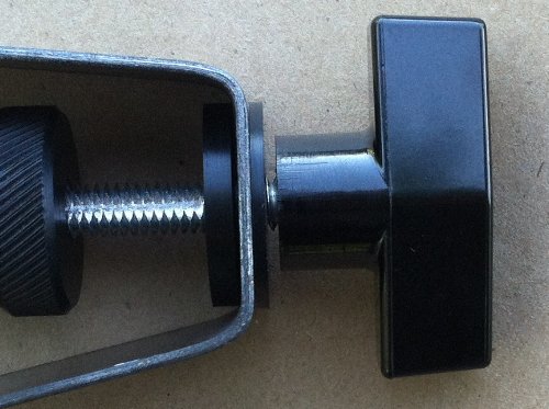
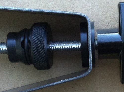
Ideally, when finished trimming the rod's length, you will end up with a "Delay Gap" that's about 1 thread wide when adjusted to "0 Turns", just like the gap located in the center of the picture below...
Step 8- Assembling the threaded shaft, "Initial Hit Dial", and "Lockup Delay Knob" onto the cylinder...
...remove the cylinder from the clutch pedal bracket
...thread the "long end" of the threaded rod into the cylinder's shaft, then secure it in place with the jam nut.
...thread the "Initial Hit Dial" onto the "short end" of the threaded rod until appx 1-1/4" of the threaded rod sticks out of the flat face of the dial.
...re-install the cylinder/rod assy thru the hole in the dash substructure and thru the Dash Bracket's Slide Bushing.
...re-install the cylinder onto the clutch pedal bracket.
...thread the plastic "Lockup Delay Knob" onto the threaded rod. Tighten it slightly until there is just enough resistance to reliably adjust the "Lockup Delay Knob" without it un-screwing from the threaded rod. With the "Lockup Delay Knob" installed, there should be a small gap between the "Lockup Delay Knob" and the "Slide Bushing" when the Delay is adjusted to "0 Turns".
Step 9- Trimming the Lower Dash's Plastic Cover Panel...
Adjusting Your ClutchTamer...
The first step is choosing a proper staging rpm that matches conditions, and produces little or no wheel spin on the start. We usually suggest creating at least a couple different "Clutch Tune-ups" for the varying conditions a street/strip car might see, but most start out with just creating a basic "Street" setting. We suggest choosing a location somewhere away from the distractions of the racetrack, just to initially get yourself familiar with the tuning process. Here are some suggested starting points for choosing a proper staging rpm...
......If your primary goal is protecting your transmission, rear diff, or drive axles from sticky tires, choose any staging rpm up to 3500 that matches conditions (little or no wheel spin), with your ClutchTamer adjustment goal of absolutely NO rpm loss from clutch drop thru the point of clutch lockup. Be sure to use the clutch pedal on all shifts.
......If you are launching on a no prep or street surface (basically more power than traction), begin with a staging rpm about 2500rpm below your engine's torque peak.
......If you are launching on an average or TNT surface, begin with a staging rpm about 500rpm below your engine's torque peak.
......If you are launching on a very sticky well prepped track, begin with a staging rpm around your engine's torque peak. After finding success there, you can work your way higher in 500rpm increments until gains level out.
Be sure to find a safe, legal, and consistent location to conduct your test sessions. A long paved private driveway usually works for us. If you are trying to simulate sticky dragstrip conditions, you might want to do some "track prep" of your own.
Above is shown the universal "shorty" underdash version of the ClutchTamer
Adjustment #1- Initial Clutch Hit...
Adjusting the "Initial Hit Dial" on the threaded portion of the shaft changes the amount of initial clutch "hit", similar to adjusting the base pressure on an adjustable long style clutch. Initially we dial in the full 10 turns of "delay" (see adjustment #2), as this basically removes the secondary clutch application and allows focusing on just the initial hit part of the adjustment. For this part of the adjustment we usually just make short 5' test hits, no need to make a full run. A data logger is nice to have, but there's an inexpensive way to get your clutch tune-up into the ballpark, just record your tach's needle movement with a Go-Pro style camera. The basic idea is to create an "upward" rpm profile where your rpm does not dip at any point between launch and the shift point.
DO NOT "PRE-LOAD" YOUR CLUTCH BEFORE LAUNCH!!! It is important to release the clutch from a properly adjusted pedal stop. Many import racers "pre-load" their clutches in an attempt to minimize parts breakage, DO NOT do this when using the ClutchTamer. Pre-loading causes less pedal travel on the "launch" cycle than during the "shift" cycles. This results in excessive clutch slip after shifts made using the clutch pedal.
Step 1- turn the "Secondary Clutch Lockup Delay" knob clockwise to a "10 turns" setting (this sets the Secondary Clutch Delay to it's maximum value).
Step 2- stage the car at your pre-selected "stage" RPM
Step 3- launch the car for appx 1/2 second while watching the tach.
Step 4a- if the engine RPM pulled down below your "stage" RPM, turn the "Initial Hit" dial counter-clockwise 1 turn then return to step 4. If the tach needle did not dip, proceed to Step 4b.
...Step 4b- if the engine RPM went more than 200 RPM above your "stage" RPM in the first 5', then turn the "Initial Hit" dial 2 turns clockwise, then repeat the step 3.
...Step 4c- if the clutch is slipping but you are experiencing excessive wheelspin, lower your "stage" RPM by 200 RPM, then return to step 3.
...Step 4d- if the engine's RPM does not dip when the clutch is dumped, and the tires do not spin in the first 5', proceed to step 6.
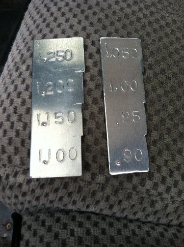
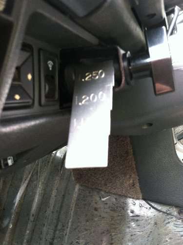
Step 5- when your ideal setting for the "Initial Hit" dial is found, measure the "Initial Hit Gap" between the flat face of the initial hit dial and the rear face of the dash bracket's slide bushing (located in the center of the picture below). This will be your BASE HIT ADJUSTMENT. Write this dimension down so it can be easily repeated. From this base adjustment, you can easily add 1 or two turns of initial hit to get a little initial wheelspeed to maximize acceleration early in the run.
Step 6- Make a "feeler gauge" the same width as the "gap" to be used to quickly get back to your base setup. Label this feeler gauge for either "Street" or "Strip" as needed. You will eventually develop many base set-ups to choose from, which will allow you to more closely match your clutch slipper setup to the conditions at hand. Below are pics of a homemade gauge set made from sheet aluminum, but plastic would work just as well and is very easy to trim with scissors. This gauge set is made in .050" increments...
 .
.
Do you have a way of logging "G's", maybe a Logger or G-Tech?...
If you have a way of logging/graphing "G's" from a launch, you will be able to get things dialed much more precisely to the conditions. Using your data, you can zero-in on your "Initial Hit" adjustment by doing little short 20' launches with the delay turned in about 7-8 turns. That allows you to concentrate only on the amount of initial hit, then use the max average G data (average of the initial horizontal ripple after wheelspin starts in) and tune initial hit to get to that G reading as quick as conditions allow without exceeding it (nicely little rounded upper transition from vertical to horizontal on the graph), then keep it smooth at that level without any ripple after the transition to horizontal. On the street w/o any prep (traction limited surface), that might be only around .80-1.0 G depending on your tires and the surface itself. Keeping the tire stuck to the surface is important, you may need to incrementally reduce your staging rpm until you eliminate the initial "G" spike that usually indicates excessive wheelspin. When traction is limited, the goal is to make that "G" graph rise as quick as possible without creating an initial spike, then keep it at that level throughout the rest of the run. Things can change a bit farther down the track when aero comes into play but basically, exceeding that ideal "G" level early in the run will likely result in wheelspin and a lower rate of acceleration.
After the initial hit gets dialed in, then you can dial back the delay from 7-8 turns and work on that. If the surface is poor, you may need to kill some power to avoid excessive wheelspin farther down the track.
TIP- If using a mechanical release (non-hydraulic), care must be taken to keep the amount of clutch pedal "freeplay" consistent as the clutch disc wears.
Adjustment #2- Secondary Clutch Lockup Delay...
The "Lock-up Delay Knob" is used to control clutch slip while the vehicle speed is catching up with engine speed. Not enough delay, the clutch locks up too quickly and either the tires spin excessively or the engine RPM dips. Turning the cylinder's winged "Lock-up Delay Knob" basically changes how quickly additional clutch pressure comes in. There are 10 turns of adjustment on the knob. At "0" turns (fully counter-clockwise), a clutch pedal delay of .181 sec was measured, barely noticeable. At "10" turns, the pedal takes about a minute to return.
Step 1-...rotate the "Lock-up Delay Knob" counter-clockwise until you can feel the added resistance to rotation when it reaches the end of it's adjustment range. This point is what we call it's "0 Turns" adjustment.
Step 2-...It is suggested that you begin your clutch slipper tuning with an initial "Lock-up Delay Knob" setting of "3" Turns. To achieve this, simply rotate the "Lock-up Delay Knob" clockwise "3" turns from it's initial "0" turns starting point.
Step 3- ...make a run thru 1st gear while observing the tach. Have an outside observer watch for tire spin.
Step 4a- ...if your tach needle rises in the first 5'-10' but then dips or the car has excessive tire spin, rotate the "Lock-up Delay Knob" by 1 turn clockwise, then return to step 3.
...Step 4b- ...if your engine rpm "flares" higher after the 1st 5'-10', rotate the "Lock-up Delay Knob" by 1 turn counter-clockwise, then return to step 3.
Basically when the car is launched, we don't want the engine RPM to dip down below the "staged" RPM. From that point we want the engine to quickly accelerate to the RPM where it makes it's peak torque, without activating the shift lite prematurely. If the rpm "flares" just after launch, it's likely you need add a little more "initial hit". If the rpm "flares" 5-10' out, it's likely you need less lockup delay.
The following delays in clutch pedal return stroke were observed with the cylinder installed in a car. The only changes made during this portion of the test was to add "turns" to the knob adjustment to incrementally add delay to the pedal return. Switches were added to the top and bottom of the clutch pedal travel, and a precision digital timer with .001 resolution attached. This pedal had an effective length of about 13", and the cylinder was attached at a point about 5-1/4" from the pedal's pivot point, an appx 2.48:1 ratio....
.000 sec delay = cylinder not attached to pedal
.181 sec delay = cylinder attached, adjustment = "0" turns in
.194 sec delay = cylinder attached, adjustment = "1" turns in
.224 sec delay = cylinder attached, adjustment = "2" turns in
.285 sec delay = cylinder attached, adjustment = "3" turns in
.395 sec delay = cylinder attached, adjustment = "4" turns in
.673 sec delay = cylinder attached, adjustment = "4-1/2" turns in
.811 sec delay = cylinder attached, adjustment = "5" turns in
1.708 sec delay = cylinder attached, adjustment = "6" turns in
When launching at higher rpms, it's very common to use delay settings up around 7-8 turns. Initially a delay setting of 2+ seconds might seem crazy, but in practice most cars will see their best overall accel G's with an aggressive high rpm hit (with just enough clutch slip to prevent rpm dip) combined with a longer 2+ second delay setting.
Of course when installed on an actual launching car, the slipper's "delay before lockup" time can depend on other factors as well. Clutch facing material is a variable, as is staging RPM and engine power output, but it takes surprising little trial/error testing to get enough results to zero in on what adjustments will work for your conditions.
Ideally, if the clutch slips just enough to hold WOT engine rpm steady from launch until the car is going fast enough to match that engine rpm, you're close to maximizing acceleration rate. Basically you want the clutch to slip just enough that the engine does not lose rpm at any point until after the shift, which insures you won't have an inertia energy discharge that can break the tires loose. I usually begin tuning clutch slip from a staging rpm near the engine's torque peak, and work my way up from there. The reason to raise launch rpm any higher than the engine's torque peak?...the higher the launch rpm, the more time the car spends accelerating free of the rotating assembly's mass. If the tires can't hold the engine's power, lowering the staging rpm below the engine's torque peak not only lowers the torque available, but accelerating the mass of the rotating assy from a lower rpm has the effect of absorbing some excess power.
NO PREP? Getting it done away from the track
If you do many street hits while datalogging, it's pretty easy to see that a typical street surface without prep is only good for .8 to .9 g's of acceleration (unless you've got really big/soft tires). Even if you prep the track to the point that your car can exceed 1g, remember that the street is still only good for .8 to .9 g's after you drive past the prep. Knowing that, just accept that the traction isn't there, and concentrate on putting down what the street WILL take, without crossing the line into excessive wheelspin.
Things you can do to maximize what you can get down...
...really loose front shocks, extend frontend travel, no binding to inhibit travel
...use softer front springs until you are just using all the travel you have
...make sure the rear suspension isn't topping/bottoming out
...move as much weight as possible from the front to the rear
...add weight as necessary (as far back and as high as possible) to make 55% to 60% rear bias
After you have done everything you can do to maximize weight transfer, take some steps to make sure the power you have does not exceed what you can get to the ground, remember- spinning isn't winning...
...lower your staging rpm until it doesn't spin on the hit
...retard the timing as needed if you need to kill excess power
...go to a more suitable rear gear to kill excess torque at the rear wheels
Some go as far as using timers or a finger button to manipulate the delay/retard boxes, basically selectively killing power for maximum effect.

If you have any questions, feel free to e-mail me