
Welcome to the internet home of ClutchTamer, we are changing the game on choosing a clutch!
Little Motor, Little Tires, Little Nitrous...
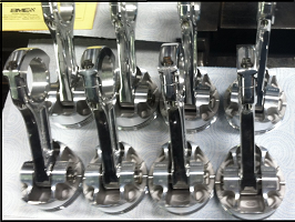
DIY Faceplating a Ford Toploader
(scroll down for the bellhousing fabrication project)
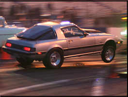
My DIY Toploader running 5.73 / 1.304 60' back in 2011 with around 700whp. It's still in the car today dead hooking over 800whp!
First A Little Background on My Venture into DIY Faceplating...
Back in 2009 I had initially turned a Saginaw 4spd into an 1/8mi crashbox in 2nd and 3rd gears, while keeping the stock synchros in 1st and 4th. It worked great for hi-rpm shifting, but the longest I could get the Saginaw's stock 3rd gear's dogs to last was 2 months of street/strip duty. Since nobody makes any upgrades for them, I decided to see how hard it would be to faceplate the Sag's 3rd gear on my own. This Saginaw project is what led me into the DIY faceplated Toploader project.
First I bought a Ford Toploader/TKO 3/4 gear faceplate slider and a couple dog rings from Liberty Gears in 2009, on the gamble that i could adapt those parts to work in my Saginaw application...
Here's the steps that i took to adapt them to the Saginaw...
...Split the Liberty faceplate slider with a cutoff wheel in a die grinder mounted to my lathe's toolholder.
...Machined the Sag's slider and 1/2 of the Liberty faceplate so i could weld the two together.
...Machined the dogs on the Saginaw's 3rd gear to allow me to weld on a Liberty dog ring.
...Due to the unique design of the Sag's mainshaft retention, i had to devise a way to release a hidden snap ring to allow dis-assembly. A little grinding on the case and a modification to a pair of snap ring pliers gets the job done.
...Assembled the mainshaft and attempted to install in the case...no way. Just couldn't get the faceplate/dog ring over the cluster. Final solution was to assemble the rear half of the mainshaft inside the case after installation.
...after it was assembled, while turning it by hand, I could feel drag from some parts rubbing. Without a way to see inside, it was hard to pin down exactly what the problem was. My solution was to take a spare Saginaw maincase and cut a big 4x6 hole in the top so I could see inside the assembled transmission. I then put the internals into my new "set-up" case with the hole in the top, and could now see that the detent on my faceplated 3rd gear needed work. Basically it over-engaged 3rd gear, causing the shift fork to rub hard in it's slot. Re-working the detent plates with a die grinder got the forks centered.
Adjusting the shifter's stops caused another problem to pop up...
...now 3rd gear's faceplate took little movement to engage, but 1st/2nd slider still travelled the original distance. Setting the shifter stop for 3rd gear resulted in 1st gear being less than fully engaged, solution was adding a stop to the shifter's body specifically for the shifter's 3rd gear lever.
...Re-installed the guts into their former maincase, installed the transmission in the car, and everything worked great.

If i could have came up with a way to faceplate 2nd gear too, i would have. Problem with that was, no way to do it and keep reverse too. Since it was a street/strip car, reverse comes in handy from time to time.
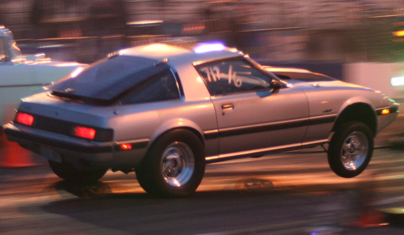
I drove it around town all the time, many trips to the track as well (about 180 mi round trip). The synchros were really nice to have for stop/go traffic, and I don't think I could have missed 3rd gear if I tried. It was a 2530lb car (with 200lb me in it) that had 45/55 distribution due to a 10" engine setback. With added fuel load it could get as much as 43/57 for the really slick back country roads, it can be neither confirmed nor denied that the car was street raced from time to time. Here's a pic of it with the custom shifter setup I made to place the shifter in the car's console opening...
Got the Saginaw down to 1.456 60' with a 6.516 1/8mi ET. Kinda wish I still had the Saginaw stuff laying around, pretty sure I could get a 2.54 ratio gearset into the 5's using my Hitmaster 2-stage clutch control system.
DIY Faceplating the Toploader
When I tore down an aluminum cased SROD overdrive Toploader, had the opportunity to compare the internals with my HEH, found a few interesting things...
...the tailhousing bolt pattern where it attaches to the main case are the same. Wasn't too hard to adapt the SROD's aluminum tailhousing to my HEH main case. Mods were done to allow the 2 shift rails to travel into the tailhousing. Speedo gear locations are different too, not a problem for me, but a split collar could be used to move the gear like in other mechanical/VSS output solutions used in the T56. Just make a collar to fit the speedo gear where you want it to set on the mainshaft, then split the collar so the parts can be assembled. Red Loctite works great for attaching the split collar to the mainshaft, no welding required.
...Mainshafts are very similar. Not interchangable without modifications, but close enough that I adapted the shorter SROD mainshaft to replace the worn HEH mainshaft for my tailhousing conversion. The web says they changed the 3rd gear bore section on the SROD. It's not the diameter that they changed, it's the length of the gear's bore. The snap ring groove moved to allow a longer 3rd (OD gear in the SROD) bore, apparently to improve oiling as that OD gear spins quite a bit faster on the shaft than a normal 3rd gear would. Easy to deal with if you have a lathe.
...1st gear is exactly the same as the 1st gear in my wide ratio HEH. Same diameter, same tooth count/pitch, synchro, same everything. Completely interchangable. Same for the 1/2 slider/hub/synchros/keys. Same as well for the countershaft itself. All the bearings appear interchangable as far as size, but the SROD's cluster gear thrust bearings are made of plastic.
...The SROD shifter design is the biggest pile of crap i've ever seen on any transmission. No idea how strong that aluminum maincase is (traditional 4 spd gearset will fit), but it would be pretty hard to find out without addressing that shifter. Maybe a modified Jeep T-176 shift tower? I know some might wonder why, I just like the adventure.
Since I took the TL apart dozens of times for this faceplate project, I made a set of mock-up bushings to use as temporary replacements for the bearings. They made it much easier to take this thing apart and put it back together quickly without having to deal with loose needles and press fits.
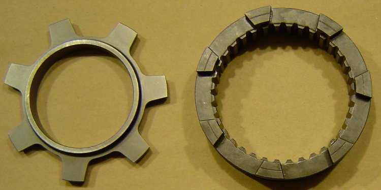
Faceplating 3rd/4th in a Toploader is common and fairly easy, but I wanted faceplated 2nd in my Toploader as well. The pic below shows a trimmed off piece of a Liberty faceplate slider sitting on the stock Toploader 1/2 slider for illustration...
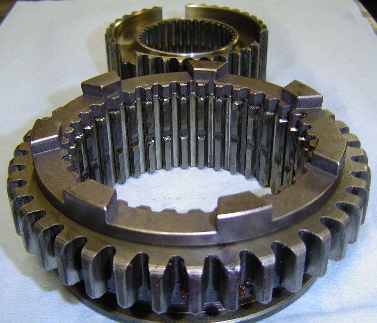
Adding the ring to the side of the stock slider increased it's overall width to 1.595", which effectively shortens the distance that the slider has to travel from 1st gear to 2nd gear. It also allows me weld the faceplate all the way around the outside without sinking the ring into the side of the gear. I narrowed the reverse gear teeth to about .485" wide, which makes room for machining a good "V" to keep the weld heat away from both the hardened dogs and gear teeth. To keep the parts aligned during the welding process, I made a fixture that pilots both parts to insure that they remain concentric. Here's the result...
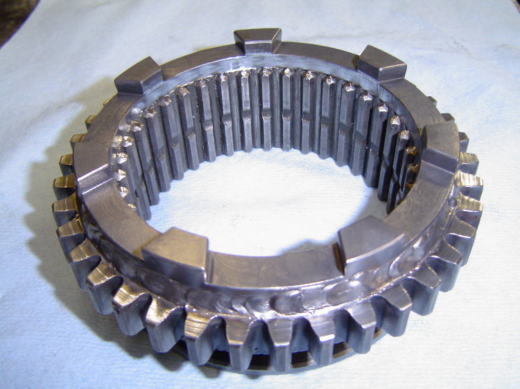
I also cut the teeth from the inner dia of the faceplate, as I realized that they do nothing as they overhang the hub when the gear is engaged. Here's a test fit of faceplated 2nd in the case...
On 2nd gear, i removed most of the little step from the backside of the Liberty dog ring so that it would press on all the way against the gear teeth. It's all a balancing act to get the best overall compromise.
I also narrowed the gaps on 3rd/4th by moving the dog ring location away from the gear teeth. I did not place the dog rings all the way on to the point that they were touching the gear, i left the shoulder behind the stock engagement lugs on 3rd, and machined a removable 2pc spacer for the input shaft as it has a smaller dia and there is no shoulder to locate against. I did notice that by spacing the dogring away from the gear on the input shaft, i had no problems assembling the transmission and didn't need to grind an angle on the front cluster gear teeth.
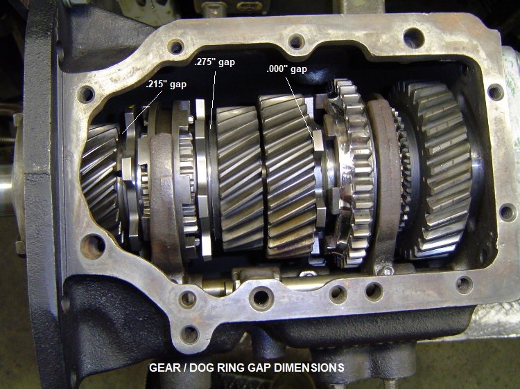
Below is a pic of the finished version of my DIY faceplated Toploader. The neutral clearance between the dog rings and face lugs is .140". The width of the reverse gear teeth on the slider has been narrowed to .485" wide, to the point that an adjustable stop is required on the reverse rail to make sure that the sliding reverse idler stops in a position that has optimal tooth contact.
When machining off the 2nd, 3rd, and the input shaft's stock engagement lugs to fit the new Liberty dog rings, you only need a snug fit for centering the ring on the gear before welding (no need for a press fit). Here's a list of the "gap" measurements between the gear teeth and the welded on dog ring teeth-
...Input shaft .215" clearance between gear teeth and dog ring
...3rd gear .275" clearance between gear teeth and dog ring
...2nd gear 0.000" clearance between gear teeth and dog ring (dog ring tight against the side of the gear teeth)
All the dog rings in this transmission were welded to the gears with a MIG welder using common .035" wire. I used a reverse skip weld pattern of 1/2" long tacks, with air blast cooling between tack welds to minimize any effect on the heat treated gear teeth and dog ring teeth. I kept tacking until the rings were completely welded 360 degrees. Same method was used to weld the faceplate to the 2nd gear side of the 1/2 slider.
Shift travel is somewhat dictated by the detent notches on the shift rails, which need to be modified to work with the shortened engagement travel distance. If you trim the notches for closer detent, the size of the ridge between notches is reduced, which changes the point/angle that the notch interacts with the rounded head of the detent pin. This increases the chance that the detent might not stop the slider/fork in the right spot due to it's inertia, could cause a jam or trying to go into 1st instead of 3rd (great reason to have a synchro on 1st instead of a dog ring). Adding internal travel limiters fixes that potential problem.
My internal travel stops were made from 3/4"od aluminum stock and would more accurately be described as stop collars, simple sleeves that fit over the shift rail between the fork and case to limit travel distance. Basically I positioned the fork where i wanted it to stop, then trimmed a piece of metal to slip into the space between the fork and case to gauge the length of collar needed. I then made aluminum collars that length, and slid them over the shift rails during assembly. the side of the collar that hits against the case will need a little grinding to make it fit against the case a little better, took me a few trial assembly's to fine tune the contour and length of the collars exactly the way i wanted them. After i was satisfied with the way everything fit together, i took it apart and drilled a hole into the stop collars so that i could put a drop of loctite into the hole after assembly, rotate the collar around a little to distribute the loctite around the shift rail, then re-position the collar against the shift fork where i wanted it. The purpose of the loctite is to prevent the collar from rotating on the rail so that the contoured end stays mated properly to the shape of the case. I used blue removable loctite, the shift rail can easily be driven thru the collar during dis-assembly.
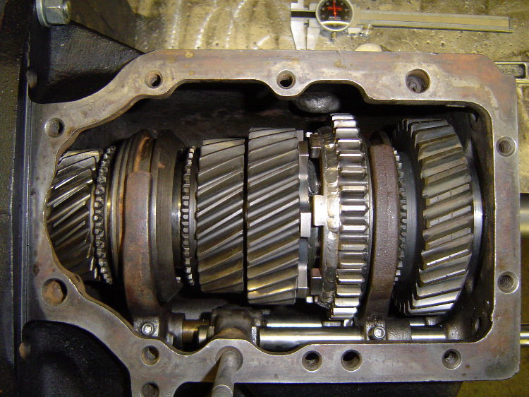
I also made another style of stop, basically a spacer inside the shift rail's bore to limit it's rearward travel. Here's a pic showing the internal aluminum travel stops in place on the shift rails. This picture was taken in August 2016 when I removed the transmission to freshen it up, it shows five years and two months worth of wear/tear on the 2nd gear engagement lugs...
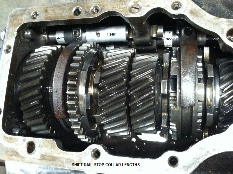
Here's a list of the aluminum stop collar lengths shown in the above picture..
...upper shift rail behind the 1/2 shift fork- .470" long
...upper shift rail in front of 1/2 shift fork- 1.945" long (end notched to fit contour of case, also includes hole for application of Loctite to keep it from spinning)
...lower shift rail behind 3/4 shift fork- .365" long
...lower shift rail in front of 3/4 shift fork- .510" long
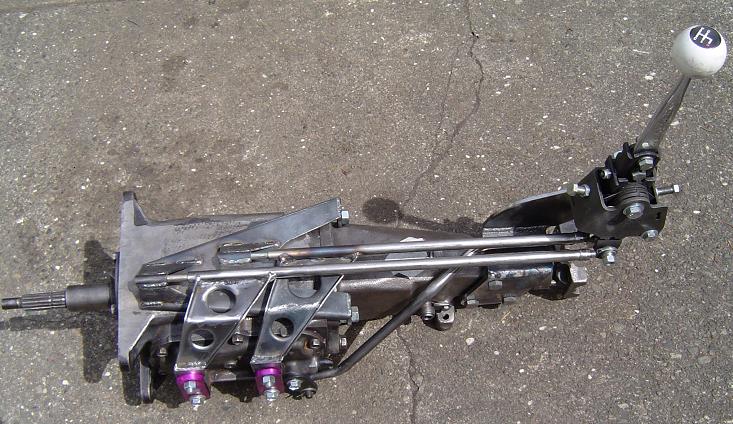
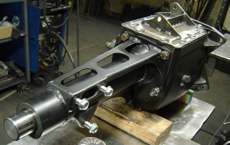
To lighten up the cast-iron Toploader, I made a .065" sheet steel tailhousing for it, eliminating the pad for the trans mount and moving the shifter mount pad to the passenger side of the tailhousing (if you look at the pic of the Saginaw shifter above, you will see why I moved the shifter bracket to the passenger side of the tailhousing). There is no trans mount on this car, but there is a crossmember under the tailhousing to stiffen the tunnel. The complete Toploader with it's cast iron main case, sheetmetal tailhousing, oil, and slip yoke weighs in at 91.4lbs. For comparison, a complete T5 with it's aluminum case/tailhousing weighs in at about 80lbs with oil. The ears welded to the top cover of the transmission are guide slots for the shifter's external rail style shift linkage (similar style to the Saginaw shifter shown near the top of the page).
As a side note, i measured my shifter throw at the knob, it's 2-1/2" from neutral into each gear, for a total of 5" of travel from 1st to 2nd gear (same for 3rd/4th). This is the result of locating the dog rings closer to the slider (away from the gear). The shifter ergonomics are great. Offsetting the shifter to above the output shaft makes it a straight push for the driver from 2nd to 3rd gear, no need for an in-line shifter.
Update as of 4/2020...�
Since i faceplated this Toploader back in 2010, it has performed VERY well, although I did break a front u-joint that took out a SROD aluminum tailhousing and bent the mainshaft back in Sept of 2011. I replaced the broken aluminum SROD tailhousing with a fabricated sheet steel tailhousing and straightened the SROD mainshaft (it was bent in 2 places). For maintenance over the last 9 years, i've only replaced a twisted input shaft, installed a new 2nd gear dog ring, and flipped the 3/4 faceplate slider to freshen the edges of the dogs. It's still got the same 28 spline SROD mainshaft that I straightened back in 2011. Thanks to those added internal shift rail stops, I have never had a problem with cracked or failed stock shift forks. My method of MIG welding the dog rings to the gears has never caused any problems either.
The car currently puts well over 800whp to the ground. This small in/small out Toploader has only needed freshening once in the last 10 years, thanks to the soft launches and shift hits of a 2-stage clutch controlled by my Hitmaster clutch control system. Here's a link to the Hitmaster info page- Hitmaster 2-Stage Clutch Control System
DIY Bellhousing Fabrication
Basically, I made my own bellhousing to adapt a Ford Toploader 4spd transmission to my old school SB Chev V8. I can buy one for around $450, but it's a heavy 1/4" thick steel monster, and I prefer building my own lighter parts if i can. I'm not concerned about it not being "SFI certified", as it's just a fun street car and i have no desire to make it legal for the track.
The mock-up began with an old 400 block and an empty transmission case. I used the alignment bar from my rearend narrowing jig to keep everything straight and true. I machined some steel pucks to fit in the block's main bearing bores and also the bearing bores in the transmission case. The pucks have an 1.501" hole in the center so that my alignment bar slides inside everything to keep the engine and transmission bores concentric. I made a ring to center the plate that the transmission will bolt to, and a tube spacer that will set the desired distance between the block and transmission face. I also made the rear plate that the transmission will bolt to, and laid out the the flange that will bolt to the block and serve as a pattern for the block plate that will fit behind the flywheel.
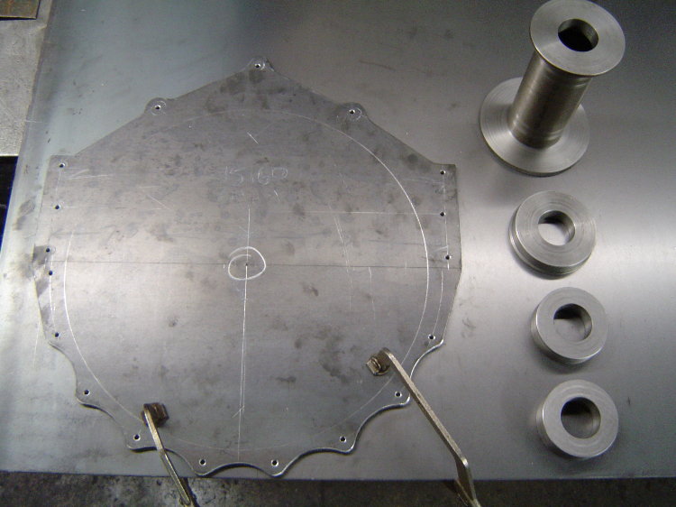
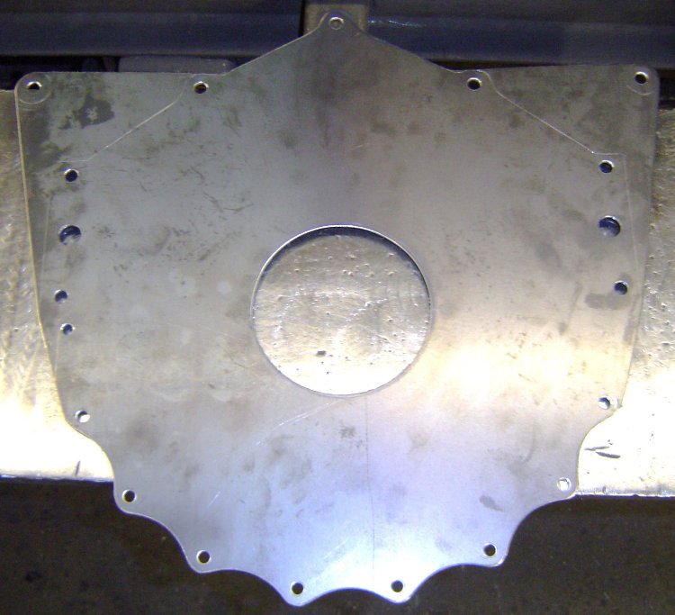
Here's the pattern I made out of 1/4" steel. All the hole locations were laid out, centerpunched, and drilled 3/16" so that the pattern could be transferred to the blank piece of 1/8" that it's laying on, which was used to make the block protection plate. The steel pucks on the right are the pilot rings and spacer that i mentioned in an earlier post that locate everything in the correct positions for mock-up. Later this pattern will get the bolt holes drilled and the large center hole will be cut out, turning the pattern into the flange for the front of the bell...
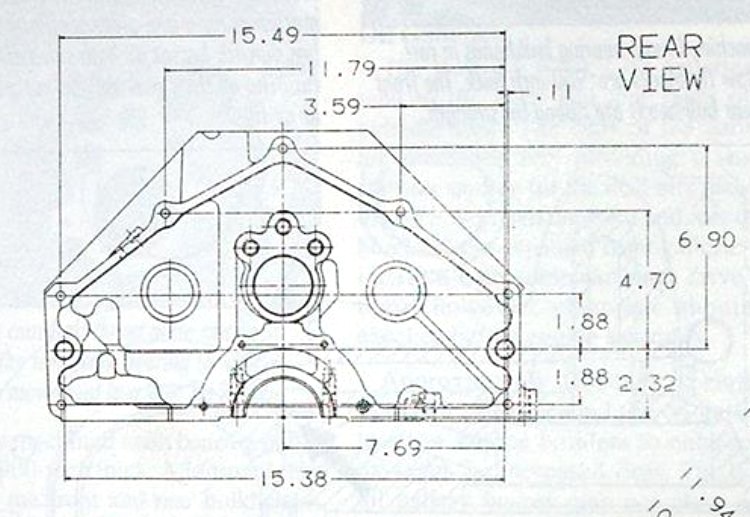
Here's the drawing I used to lay out the block bolt pattern...
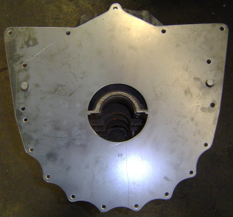
This is the block plate after it was cut out and drilled. The large hole in the center is for the crank's flywheel flange to stick thru, and the 2 larger holes on the sides are for the locating dowels in the block...
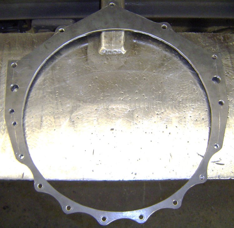
This is the pattern after i drilled it out and cut the center out. It is going to be the forward flange of the bellhousing that bolts to the block, the large hole in the center is necessary to clear the flywheel...
Here's the block plate on a block. The upper "wings" were added as mid-mounting points that will hang the back of the engine at the firewall...
Here's the block plate and flange on a block. The block plate will be sandwiched between the block and bellhousing as shown. I'll soon be creating a hole and pocket for the starter.
Here's a pic of the rolled ring welded to the bellflange. All the holes still fit perfectly...
The mid-mounts incorporated into the block plate allow me to easily remove the bellhousing/clutch/flywheel from the car without needing to support the engine. Greatly simplifies my clutch and transmission maintenance.
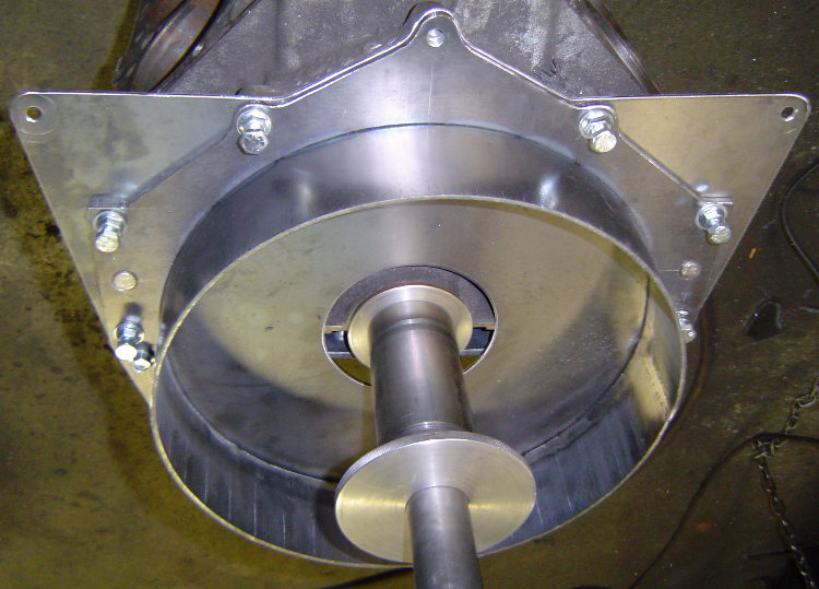
Here's the alignment bar in place in the block, as well as the spacer that sets the depth between the block and trans case...
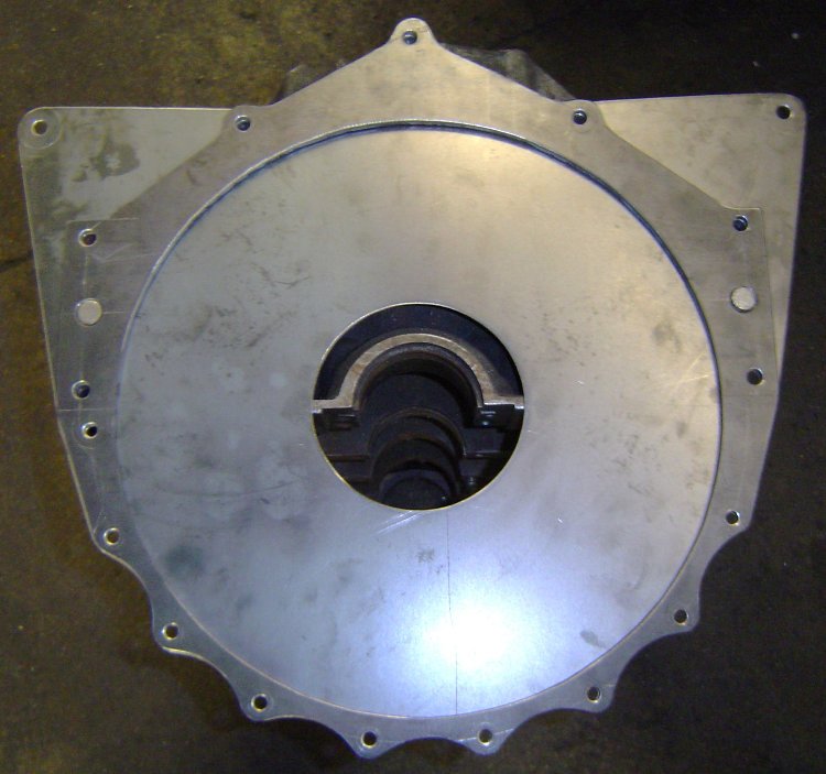
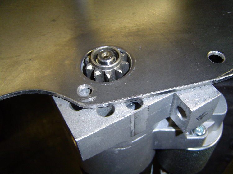
Here's the trans case in position located by the pilot rings...
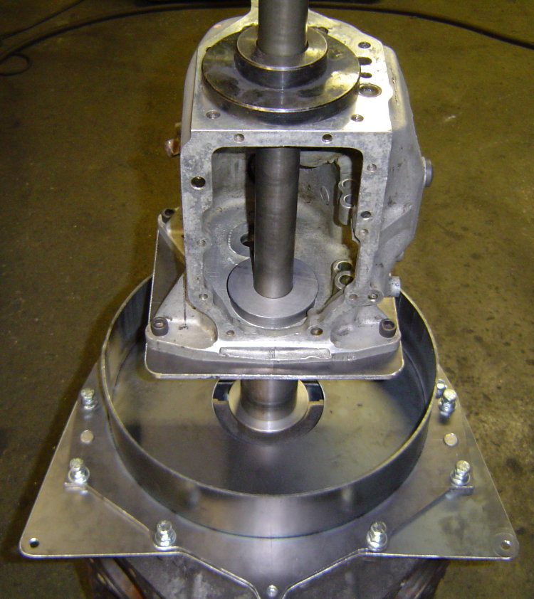
I had to take it out of the fixture to make sure i had created enough room to install a SoftLoc clutch, so i figured i'd snap a few pics of the progress.
I started making patterns for closing in the bell by laying out the the top section on posterboard. I quickly realized it was much easier to just cut out slightly larger pieces of posterboard, hold them in place on the bell, and simply apply a little pressure by running my finger around the edges of the steel. This puts a small crease in the posterboard and transfers the exact shape needed, a much quicker way to create a pattern...
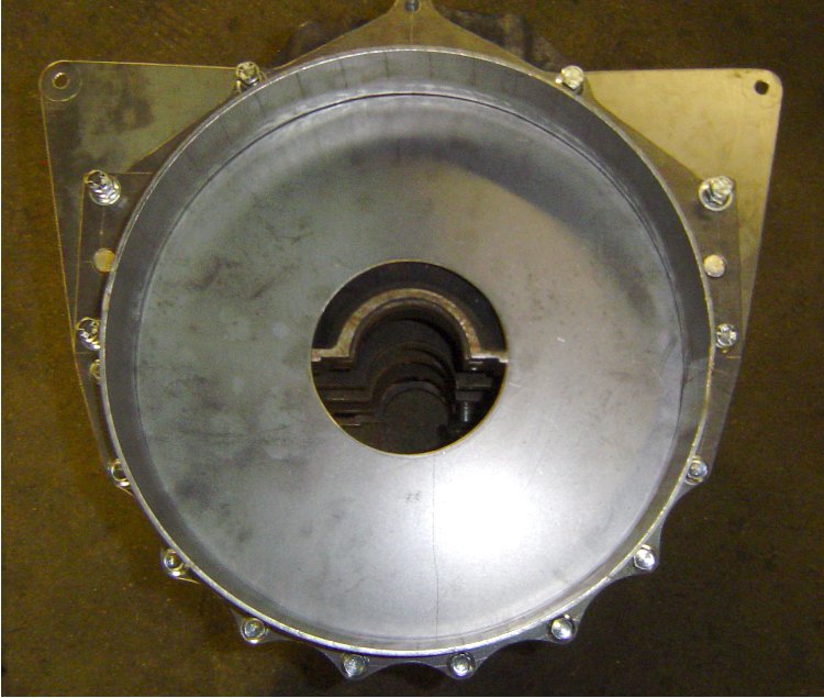
In this pic the transmission plate was still tacked in just 4 places. After all the rest of the inside/outside welding was done, I put the bell back on the alignment fixture, cut those 4 tacks, then re-positioned the trans plate with the alignment fixture in place before finish welding the plate. The result was the bell came off the fixture already "dialed-in", with no need to adjust the dowels or machine the mating surfaces.
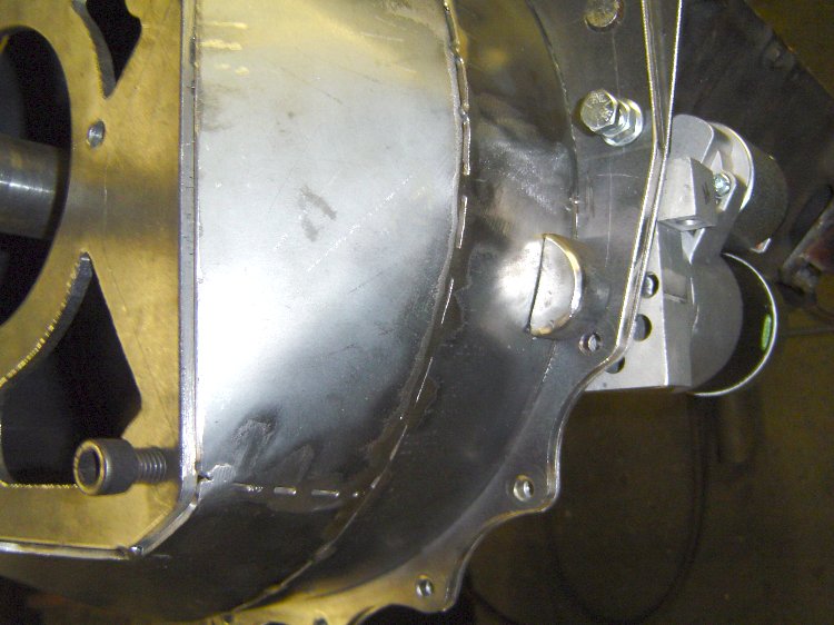
Added a cutout for the mini-starter's drive...
Added a starter pocket to the bell as well...
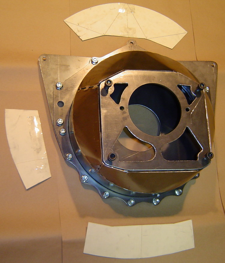
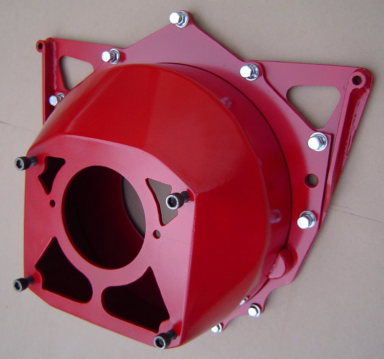
Here's the finished product...
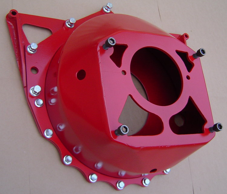
UPDATE-...I went to a 3pc style bellhousing...blockplate, midplate, bell/can. Now i can remove the engine from the car with the flywheel and clutch, and leave the bell and transmission mounted in the car. I can also remove the transmission/bell/clutch/flywheel from the car without supporting the rear of the engine. I also added a couple external "ears" to the block plate, which gives me some easy attachment points for lifting the engine...
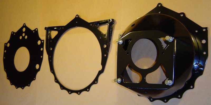
My fabricated bell, including the mid-plate, block protector, and hardware, is 26.2 lbs.
CHANGING THE GAME ON CHOOSING A CLUTCH FOR YOUR CAR!!