Little Motor, Little Tires, Little Nitrous...
DIY Balance Checking Fixture
(scroll down for the bellhousing fabrication project)
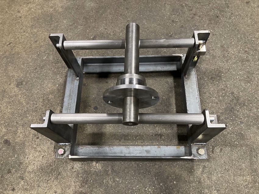
Check balance of flywheels / pressure plates / clutch discs / wheel hubs / rotors without sending them to the balance shop
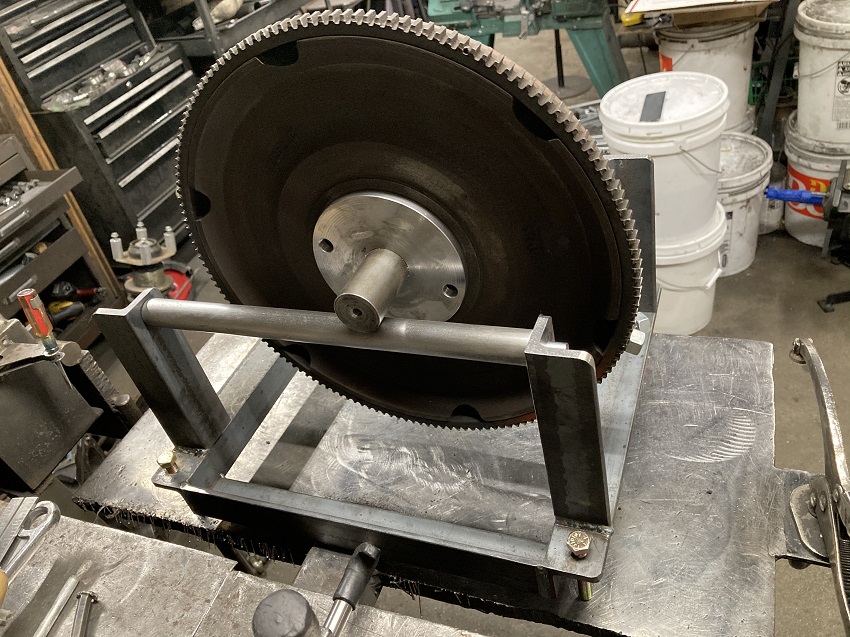
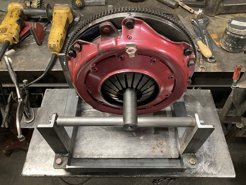
Here's a simple balance checking fixture I made, wanted something to quickly verify flywheel and PP balance at home. This was my first pass at this using materials I already had on the rack, basically angle iron and some cold rolled shafting. The arbor in the pic above is single purpose, made to duplicate the fit of my crankshaft's flywheel flange/pilot. First the flange was rough turned, then bored to fit the shaft which was then secured in place using red loctite. Then the shaft was set up for zero runout in the lathe, after which the flange itself was finish turned to the exact same size as the crankshaft pilot.
This static flywheel/clutch balancing thing is probably seen as a hillbilly hack at first glance. When a crankshaft is dynamically balanced, most shops balance using the end counterweights, basically balancing each end of the assembly separately. Same for a driveshaft. But when you think about balancing a typical flywheel, dynamic balancing doesn't really bring much to the table as the guy doing the drilling is probably going to drill on the backside of the rim either way. Same for the pressure plate, not really a lot of choices of where to remove or add weight. That coupled to the fact that something dynamically balanced is automatically going to be in static balance as well, static balancing the flywheel first and then balancing the pressure plate bolted to an already balanced flywheel makes practical sense, and gives you the same basic location separation that you get with dynamic balancing.
Turned out it works pretty good for what it is, detects an an out of balance 1 gram on a 6" radius when you set it up on a very rigid surface like a concrete floor. I use it to verify neutral balance of the flywheel first, then add the pressure plate to further balance the assembly.
ADJUSTMENTS- To adjust parallel of the support shafts, i just lay the face of the flywheel across both shafts and check to see if it rocks, then adjust until it doesn't rock. Front to back level I adjust with a digital level, side to side i level by letting the arbor roll on the support shafts until i'm satisfied it has an equal tendency to roll in both directions.
NOTE- The components I balanced here were all for an internally balanced engine. If one wanted to duplicate the imbalance of an existing counterweighted flywheel, an offset weight could be added to the arbor for the purpose of bringing the arbor/flywheel assembly into neutral balance. That counterweighted arbor could then be used to verify that a new flywheel is the same counterweight specification as your existing counterweighted flywheel.
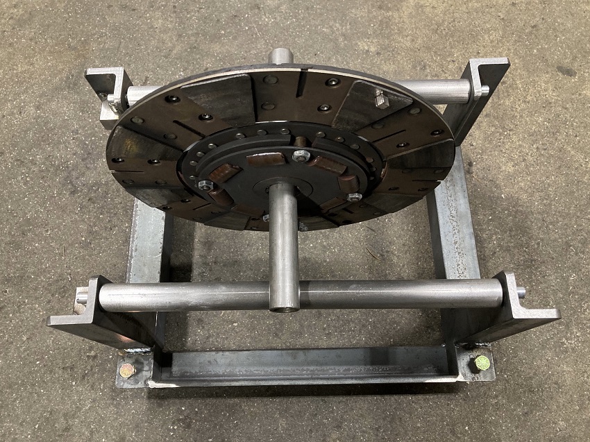
Here's some pics with an old cast flywheel i had laying around, here you can see the leveling screws installed in the base...
Here you can see that one end of the support shafts non-adjustable, just holes for the pins that are threaded into the shafts...
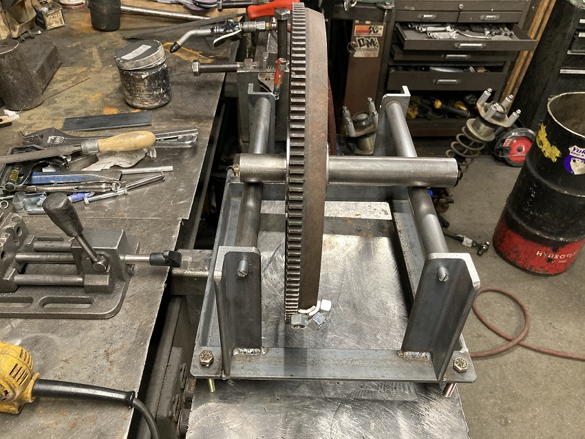
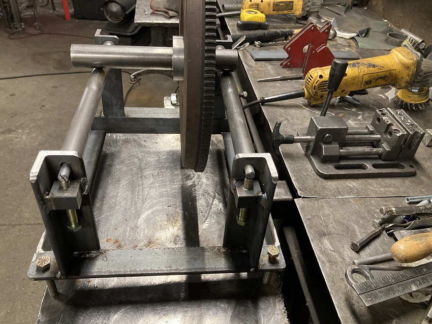
Here you see the other end of the support shafts, which go into slotted holes with adjustment screws to allow adjustment for parallel of the support shafts...
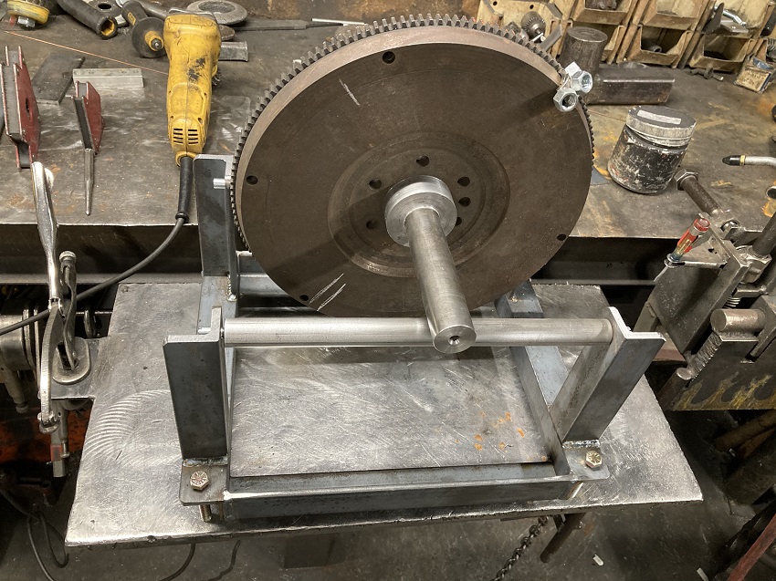
Here you can see that the old flywheel, supposedly neutral balanced originally, required 43 grams applied to it's rim to achieve neutral balance...
After verifying that the fixture worked as intended, I then static balanced a 19.3lb steel flywheel that I had been using on my 355. Sorry, forgot to write down exactly how much weight it took before I started drilling. I had taken a little weight out of the backside a while back, i'm guessing it took about 12g to bring it into static balance.
With the flywheel zero'd out, I then bolted a 16.7lb Ram diaphragm pressure plate on to check it's balance. Turns out it needed 22g. I then rotated the PP 180 degrees on the flywheel and checked it again to verify. Took the same 22g on a 5-1/8" radius in the same "6" location. Looks like depending on how the two were bolted up before, balance of this assembly could have been out a minimum of 10g or a maximum of 34g overall. Ram says they balance to .5 ounce inch, that's about 2.5 grams at the radius i'm working with. That has me feeling pretty good about the 1 gram resolution i'm getting from the cold rolled shafts. Since the added weight needs to be added at the "6" location, i'm going to take advantage of the coincidence and install a shouldered stud in the #6 cover bolt position, then make an appropriate balance weight to install on that stud.
This used dual friction disc was only out 1g @ ~ 5". I'm also going to make arbors to check balance of my front hubs and brake rotors as well.
Originally resolution of this fixture was 2 grams, but I soon found that if set up the fixture on the concrete floor instead of the not so rigid bench plate, resolution improved to 1g with the cold rolled shafts. The 65lb bench plate in the pictures plugs into a single 2" square receiver style socket in the bench, turns out it moved a little when the weight of a flywheel/PP were rolled from one side to the other. Setting the fixture up on a concrete floor fixed the problem.
DIY Custom Steel Bellhousing Fabrication...
Basically, I made my own bellhousing to adapt a Ford Toploader 4spd transmission to my old school SB Chev V8. I can buy one for around $450, but it's a heavy 1/4" thick steel monster, and I prefer building my own lighter parts if i can. I'm not concerned about it not being "SFI certified", as it's just a fun street car and i have no desire to make it legal for the track.
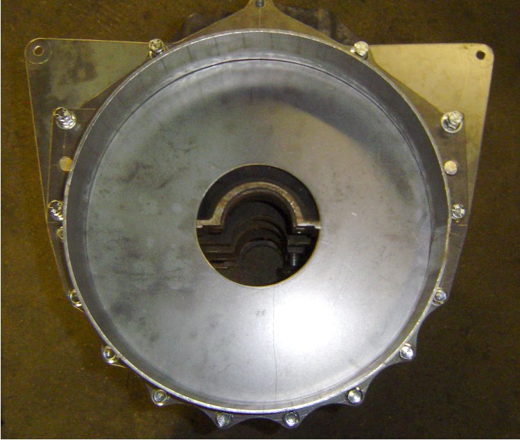
The mock-up began with an old 400 block and an empty transmission case. I used the alignment bar from my rearend narrowing jig to keep everything straight and true. I machined some steel pucks to fit in the block's main bearing bores and also the bearing bores in the transmission case. The pucks have an 1.501" hole in the center so that my alignment bar slides inside everything to keep the engine and transmission bores concentric. I made a ring to center the plate that the transmission will bolt to, and a tube spacer that will set the desired distance between the block and transmission face. I also made the rear plate that the transmission will bolt to, and laid out the the flange that will bolt to the block and serve as a pattern for the block plate that will fit behind the flywheel.
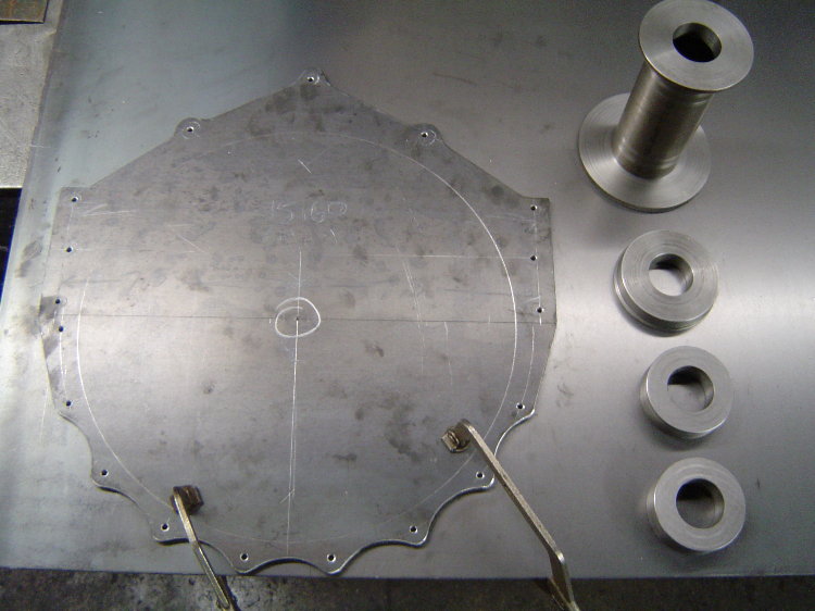
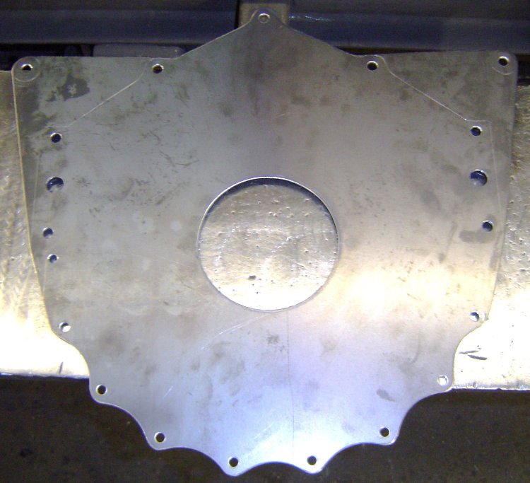
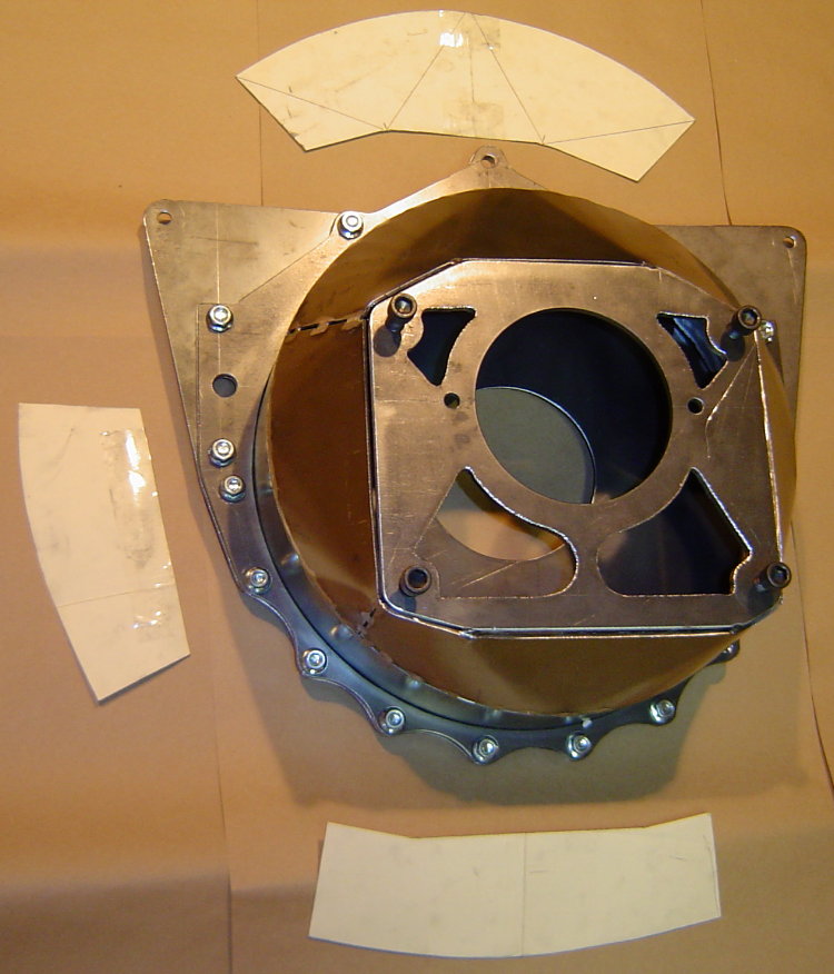
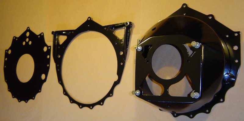
Here's the pattern I made out of 1/4" steel. All the hole locations were laid out, centerpunched, and drilled 3/16" so that the pattern could be transferred to the blank piece of 1/8" that it's laying on, which was used to make the block protection plate. The steel pucks on the right are the pilot rings and spacer that i mentioned in an earlier post that locate everything in the correct positions for mock-up. Later this pattern will get the bolt holes drilled and the large center hole will be cut out, turning the pattern into the flange for the front of the bell...
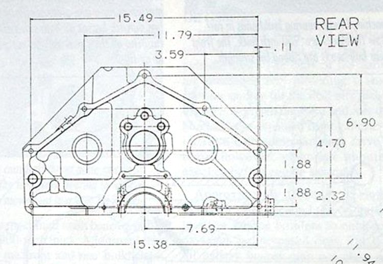
Here's the drawing I used to lay out the block bolt pattern...
This is the block plate after it was cut out and drilled. The large hole in the center is for the crank's flywheel flange to stick thru, and the 2 larger holes on the sides are for the locating dowels in the block...
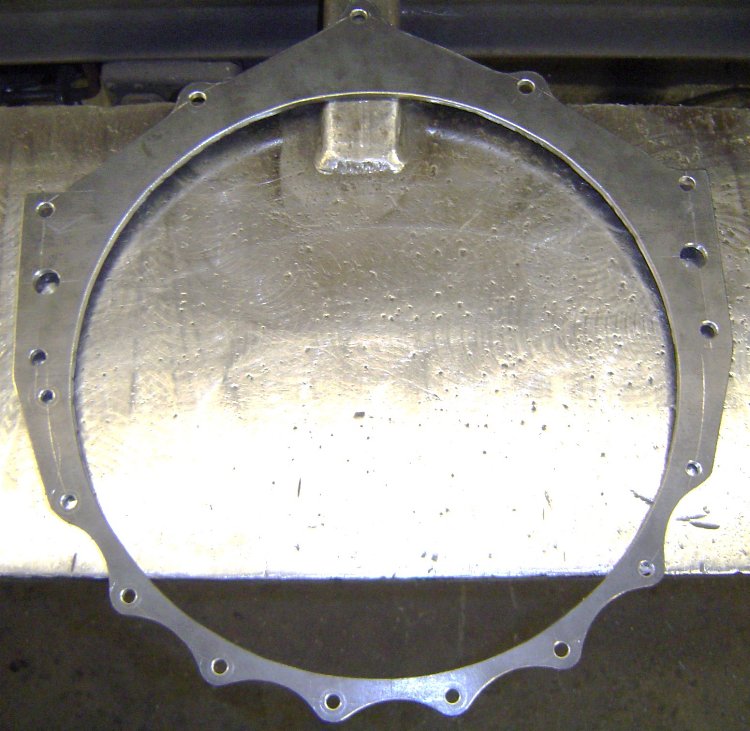
This is the pattern after i drilled it out and cut the center out. It is going to be the forward flange of the bellhousing that bolts to the block, the large hole in the center is necessary to clear the flywheel...
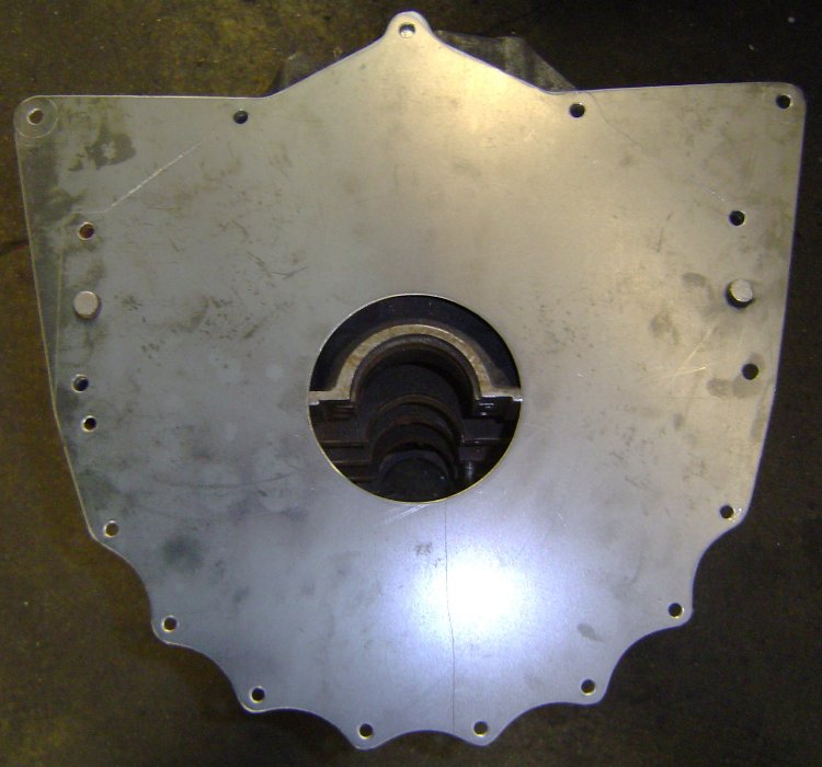
Here's the block plate on a block. The upper "wings" were added as mid-mounting points that will hang the back of the engine at the firewall...
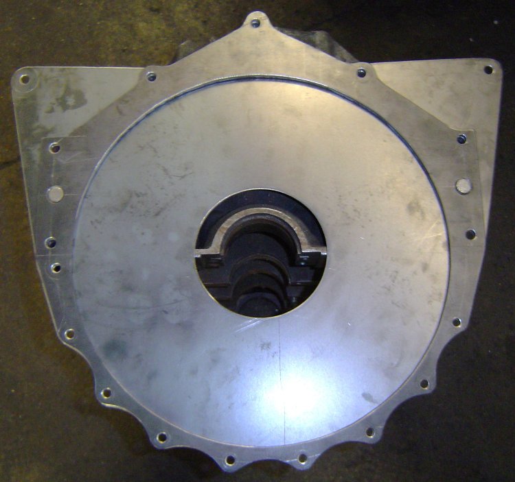
Here's the block plate and flange on a block. The block plate will be sandwiched between the block and bellhousing as shown. I'll soon be creating a hole and pocket for the starter.
Here's a pic of the rolled ring welded to the bellflange. All the holes still fit perfectly...
The mid-mounts incorporated into the block plate allow me to easily remove the bellhousing/clutch/flywheel from the car without needing to support the engine. Greatly simplifies my clutch and transmission maintenance.
Here's the alignment bar in place in the block, as well as the spacer that sets the depth between the block and trans case...
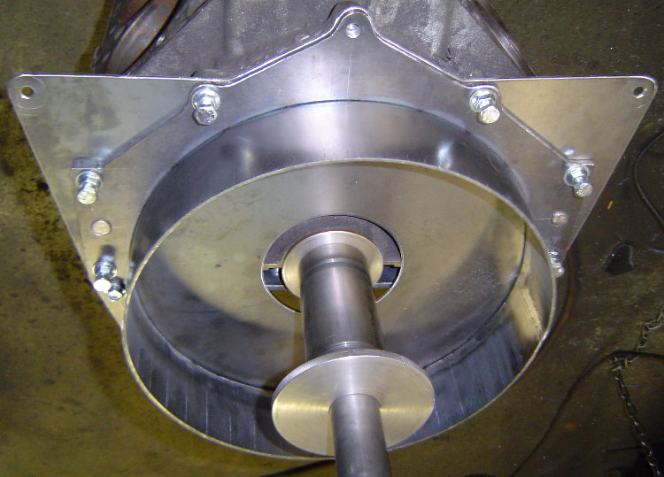
Here's the trans case in position located by the pilot rings...
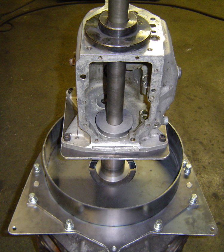
I had to take it out of the fixture to make sure i had created enough room to install a SoftLoc clutch, so i figured i'd snap a few pics of the progress.
I started making patterns for closing in the bell by laying out the the top section on posterboard. I quickly realized it was much easier to just cut out slightly larger pieces of posterboard, hold them in place on the bell, and simply apply a little pressure by running my finger around the edges of the steel. This puts a small crease in the posterboard and transfers the exact shape needed, a much quicker way to create a pattern...
The transmission plate is still only tacked in 4 places. After all the rest of the welding is done, i'll put the bell back into the fixture, cut the tacks, and re-position the plate for the best alignment possible before welding it in place. I doubt there will be any need to machine the block or transmission mating surfaces.
Added a cutout for the mini-starter's drive...
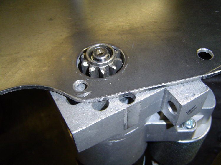
Added a starter pocket to the bell as well...
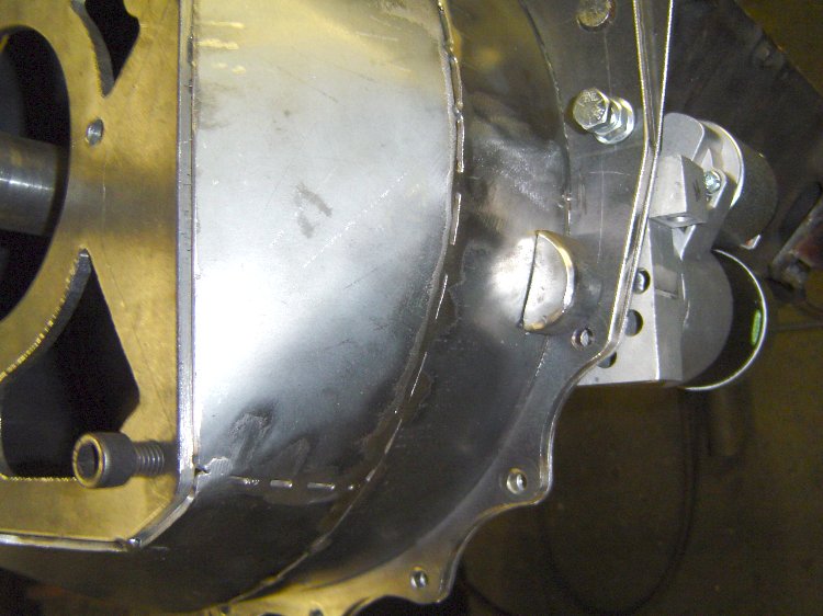
Here's the finished bellhousing...
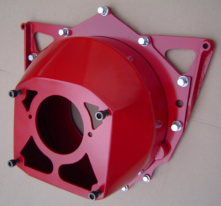
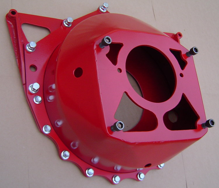
UPDATE-...I went to a 3pc style bellhousing...blockplate, midplate, bell/can. Now i can remove the engine from the car with the flywheel and clutch, and leave the bell and transmission mounted in the car. I can also remove the transmission/bell/clutch/flywheel from the car without supporting the rear of the engine. I also added a couple external "ears" to the block plate, which gives me some easy attachment points for lifting the engine. I also made the center hole in the block plate larger, more air circulation to cool the clutch down quicker...
I'll take some pics of the engine lifting fixture i made for it. It plugs into the blockplate's added "ears" and into an "eye" that screws into a hole in the top of the waterpump. It fits over the complete engine with the aircleaner and distributor in place. Before i was always using some type of hokey chains trying to find a perfect balance point without damageing something. Now i have a dedicated fixture that plugs in and makes the job easy. Been thinking about attaching the radiator to the engine just to make choosing between a couple engines that much easier
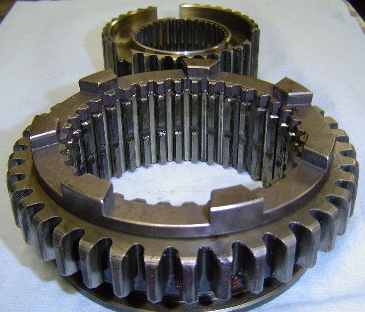
DIY Custom Faceplating of a Ford Toploader 4 Spd...
Who says you can't DIY faceplate 2nd gear in a Ford Toploader? Parts for 3rd & 4th gear conversions are available off the shelf from Liberty, but Proshift was the only upgrade available for 2nd. I took a set of 3rd/4th Liberty parts and modified them to fit...
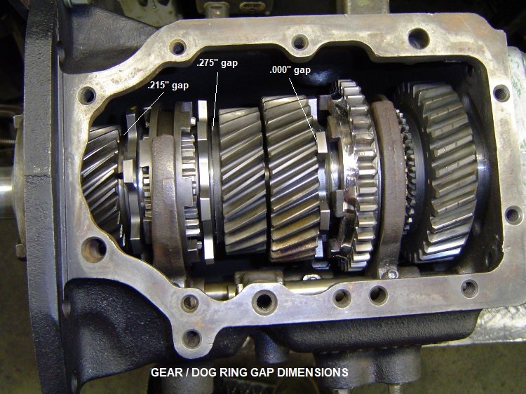
Here's a pic of a trial fitting of 2nd inside the main case. The Toploader now has been faceplated in 2nd, 3rd, and 4th gears. Keeping the 1st gear synchro makes it easier to drive on the street, as you can slip it in and out of gear while idling at a stoplite. If you decide to faceplate your own Toploader (or have a local shop do it for you), this pic also shows the gap dimensions I use which tighten up the slider travel distance quite a bit over what you get when Liberty does it. My shifter knob travel is 1-1/2" from neutral in each gear, which translates to 3" overall arm movement when shifting...
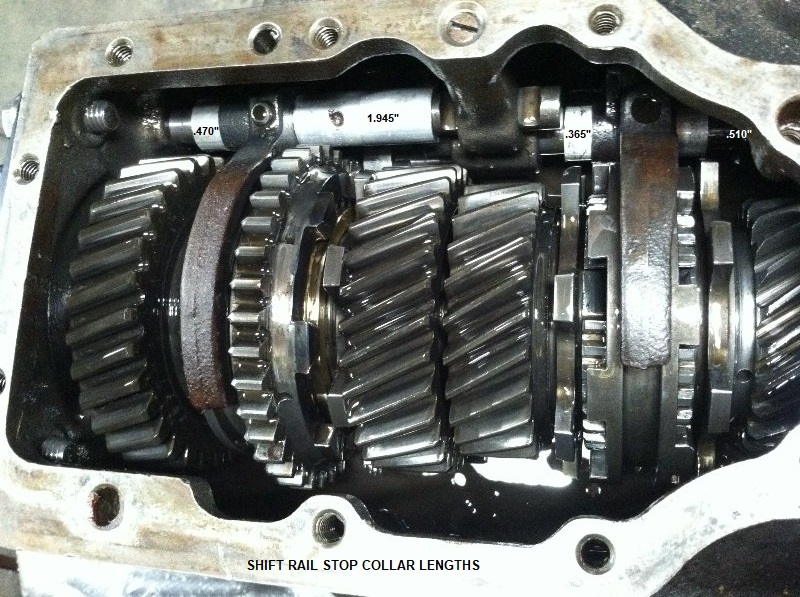
Here's the same transmission as above, except 5 years later. You can see some rounding of the edge of the 2nd gear dogs in this pic, we pulled the trans down to replace them. What you can also see is the aluminum shift rail stops we added on both sides of the shift forks. This greatly reduces the hammering effect of the rail's inertia on the forks, we have had no problems with bent or broken stock shift forks at all. This pic also shows the stop collar lengths that I use...
I originally bought 3 TKO dog rings and 2 TKO faceplate sliders from Liberty. Back in 2011 the dog rings were $65/ea, the sliders were $100/ea....
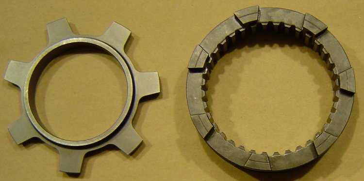
Machined the gears to accept the dog rings. Liberty slider for 3rd/4th gears was used as-is, no modifications. For the 1/2 slider, I slit one side off the extra 3/4 faceplate slider, then welded it onto the 2nd gear side of a stock Toploader 1/2 slider. Retained the original synchro setup on the 1st gear side. Ended up with synchro 1st, faceplated 2/3/4. Here's a pic of the parted off section of Liberty faceplate slider sitting on the stock slider...
Here's a pic of the slider after welding on the faceplate ring. Note that reverse gear teeth on the stock slider were narrowed to make room for the weld, the inner teeth of the faceplate ring were also removed...
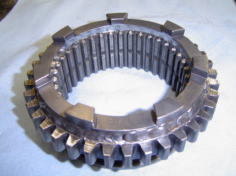
All this was skip welded using common .035" MIG wire, air blast cooling between welds to protect the heat treat of the engagement lugs.
This transmission has been in the car for around 10 years now, no broken gears, shafts, or shift forks to date. I have replaced faceplate parts a few times due to wear/tear, also replaced a few twisted small input shafts and Spicer 28spl slip yokes. Still has the same 28spl SROD output shaft that was installed in 2011, it's splines are still straight. Went to a 28spl billet Sonax slip yoke a few years ago, it's splines are still straight as well. Car is currently using a Hitmaster clutch hit controller. It's configured to soften the hit for around 1.0 sec during launch, but also comes on for 0.5 sec after the shifts. Without the unit active for WOT shifts, the Toploader's small input shaft splines twist.
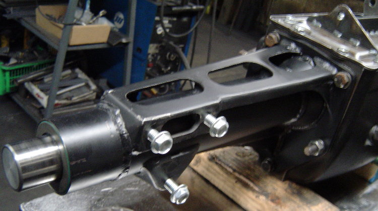
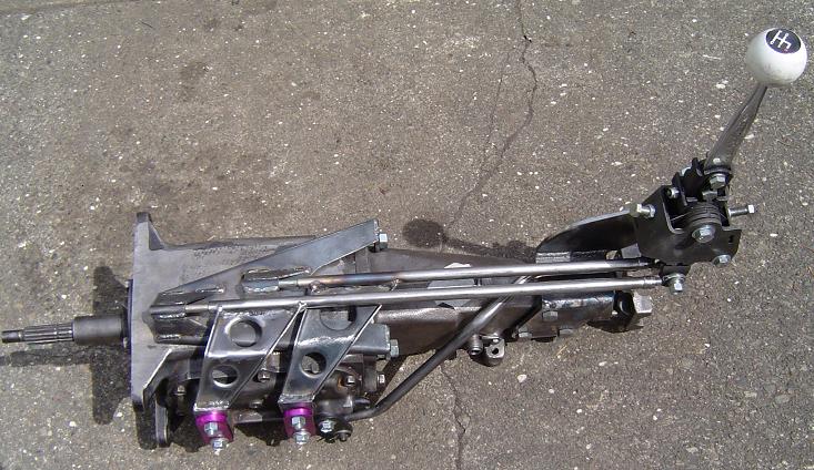
To lighten up the cast-iron Toploader, I made a .065" sheet steel tailhousing for it, eliminating the pad for the trans mount and moving the shifter mount pad to the passenger side of the tailhousing (allows fabrication of a smaller/lighter shifter mounting bracket). In this pic you can also see the external "rail style" shift linkage guides that are welded to the Toploader's original sheetmetal top cover. This style linkage allows mounting the shifter above the output shaft, overall it's similar to the Saginaw shift linkage shown two pictures below...
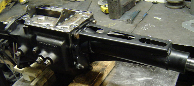
Fabricating our own tailhousing from steel saves weight over aluminum due to use of thinner materials, also allows for a more efficient shifter bracket location. There is no trans mount on this car, but there is a crossmember under the tailhousing to stiffen the tunnel. The complete Toploader with it's cast iron main case, sheetmetal tailhousing, oil, and slip yoke weighs in at 91.4lbs. A complete T5 with it's aluminum case and tailhousing weighs about 80lbs with oil.
I don't have a picture of the shifter installed on the Toploader, but it is basically just like the one pictured below that i made for a Saginaw 4spd back around 2008. Looking at this picture you can see why I moved the shifter mount to the right side of the fabricated Toploader tailhousing...
This puts the shifter up in the perfect spot for the RX-7's console opening. The short stick, combined with the tightening up of the Toploader's faceplate spacing, reduces the shifter's total "throw" to only 2".
Original Prototype of the ClutchTamer Clutch Hit Controller...
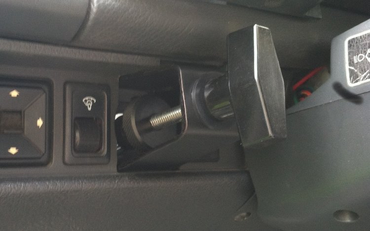
In the beginning i was just looking for a way to reduce transmission breakage, but I soon found it had much more potential than just saving parts. Basically it was a small hydraulic screen door closer cylinder that connected to the clutch pedal with a simple bracket. This was the original prototype version of the ClutchTamer...
Turning the black knob adjusted the clutch pedal's release rate, adjusting the inner dial on the threaded rod moved the point in pedal travel that the cylinder becomes active. It was an effective, no hassle way to completely eliminate any sign of a bog, and almost made it too easy to hook radials with a stick.
The above slip controller was used on a 2800lb Ram diaphram pressure plate, and a Ram sintered iron disc. It was a more street-friendly alternative to the high-maintenance Mcleod SoftLoc clutch, which uses a Long style PP that needs frequent adjustments of the spring pressure and occasional pressure plate shimming. My version can easily be adjusted from the driver's seat, and does not effect normal street driving.
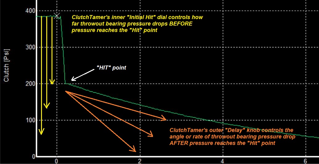
Here's a graph showing typical shape of the throwout bearing PSI curve with the ClutchTamer controlling clutch engagement...
The Clutch Slipper project has evolved a bit, and has become a business all it's own. Check it out here at ClutchTamer.com
Original Prototype of the HitMaster 2-stage Clutch Slip Controller...
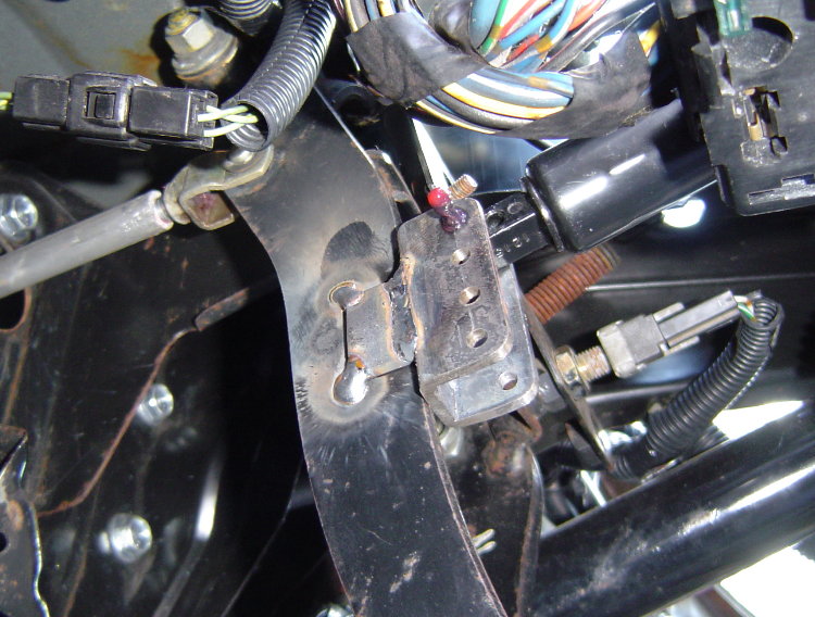
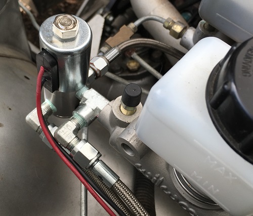
My Shop Mule car was the original testbed for developing the HitMaster 2-stage clutch hit control system. Pic on the left shows the system's 2nd stage transition valve installed on the Shop Mule's clutch master cylinder...
 .....
.....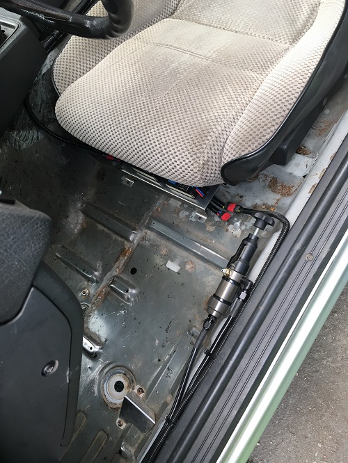
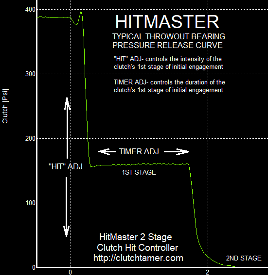
Pic on the right shows the HitMaster valve and dual timer install inside the Shop Mule. The timers are mounted to the aluminum panel that's almost hidden under the front edge of the seat. Left timer sets the clutch transition point after launch, the right timer sets the clutch transition point after the shifts. Here's a graph showing typical shape of the throwout bearing PSI curve with the Hitmaster System controlling clutch engagement...

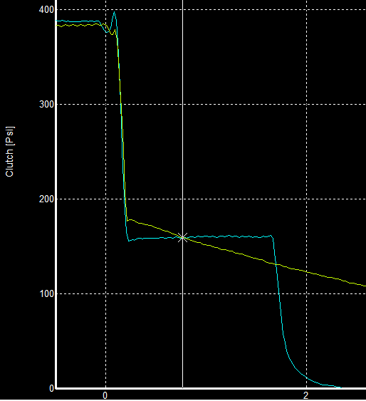
Here's a graph showing a comparison of the ClutchTamer and Hitmaster release curves. Let's say the ideal hit for a given chassis would be about 160psi, which happens to be about where the two traces intersect. The ClutchTamer's degrading curve needs to hit above 160psi in order to keep from dropping below 160psi too quickly. The stepped shape of the Hitmaster curve allows psi to drop instantly to the sweet spot, so it hits a little harder without danger of dropping past the sweet spot too quickly...
A while back I was making some HitMaster no-prep NA test hits using a 10.4" Ram dual friction organic/metallic disc, combined with a Ram 2800lb diaphragm PP. Normally a dual friction disc combined with a 2800lb pressure plate would be waaay too aggressive for a no-prep application, but this one has it's hit softened by the system mentioned above. The Shop Mule has a 2.78 1st gear, 3.73 rear gear, and 28" M/T 275 radials @ 28psi. Initially the transition timer for the clutch was set to 1.0sec. I fired the car up, drove a few miles from the shop to warm the oil up a bit, then stopped to make a hit. Dead cold 275 radials on a random stretch of chip sealed county road, zero rubber down with no burnout at all. The 4500 clutch dump produced a dead hook launch with a peak of 0.98 G's @ 1.02sec. When the 2nd stage of the clutch kicked in at 1.0sec, it knocked the tires loose and as a result the accel G's dropped to .72.
I later did basically the same routine, except this time I bumped the transition timer setting up to 1.5sec. This time a 4900 clutch dump produced another dead hook launch with a higher 1.22 G peak @ 1.8sec in, well after the clutch's transition point. That simple addition of 0.5 sec to the transition timer setting improved peak accel by .24G's, also got the car to 50mph about .625sec quicker. No other changes between those two hits, just that .5sec addition to the clutch transition timer setting.
Dead hooked radials from a 4900rpm clutch drop on a random chip sealed county road with zero surface prep and no burnout at all. The dual friction disc doesn't complain at all about the 1.5sec slip time that it takes to bring it all together on the zero prep surface.
To find out more about the HitMaster 2-stage clutch hit control system including how it works CLICK HERE
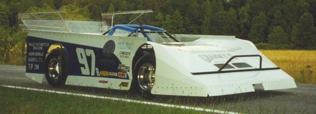
Be sure to check out the page featuring my 4 rotor rotary powered Outlaw Dirt Latemodel that i built back in 1995.
CLICK HERE to go to the 4 rotor latemodel page.